Elevated radials not equal to ground plane
A common misconception is elevated radials (as counterpoise) perform the role of “ground plane” in an antenna system including dominating the far field effects from real ground over which the antenna resides.
Radials perform two roles: a conductive path for the inner shield currents and a method to ensure the radiation from this new path is cancelled in the far field. Let’s dig further by examining the two roles.
A conductive path for inner shield currents
Almost everyone knows the RF currents within a coaxial transmission line have two equal and opposite polarity components. The current from the center conductor energizes the monopole… easy enough. The current on the inside of the shield has many more pathways to follow. Notably, the outside of the coax can entice the current to flow depending on what impedance it presents to the antenna feedpoint. If the antenna electrically connects to the mounting structure, it too can entice currents to flow.
Enter a single radial…
A conductor trimmed to 1/4 wavelength at the operating frequency is a form of impedance transformer. Since the free end of the radial is open, it maintains a high impedance by definition. Following the transformer logic, this high impedance transforms to a low impedance at the other end. If we connect this Low Z point to the shield/mounting-structure at the feedpoint, it will provide a low impedance and tend to draw a large proportion of the inner shield current to itself. This radial, thus energized, radiates. We have solved half the problem with monopoles… namely we have reduced the current flow on the outer transmission line and mounting structure by monopolizing the current flow into the radial with its manufactured low impedance at said feedpoint. This logic doesn’t necessarily hold true if the outer shield of the feedline or mounting structure also presents a Low Z in parallel with the radials, but let’s assume for the moment the radials win the “current” battle. With current flowing upon it, the single radial is free to radiate its energy exactly like the monopole element.
Canceling far field effects by adding another radial…
If we add a second radial opposite the first, the same action occurs with both receiving the lion’s share of current divided equally between them. The symmetric orientation of the two radials is such each both radiate, but because their polarities are opposite each other by way of orientation, the far field summation from both is negligible. It isn’t zero, but is so small to be of no consequence so long as the radials are 1/4 wavelength or less.
Two problems solved
Thus providing two radials, one opposite the other, solves two problems for us: manhandling the shield inner current and ensuring this current doesn’t affect the far field of the antenna pattern.
What tests have to say
Simulation and direct measurement both confirm just two radials of 1/4 wavelength or less result in almost zero perturbation of the monopole far field radiation pattern leaving the monopole element alone in determining the radiation circular symmetry.
Note the induction fields (stored energy fields) of each radial are not balanced in the near-field. Thus it is possible to greatly perturb the far-field balance if one radial is too close to some mounting structure or another conductive object. With each radial containing half the shield current energy, they are each more sensitive to nearby conductors.
Add more radials
Continuing the theme, adding more radials almost completely eliminates any microscopic deviation from a pure circular far-field pattern. Three or four radial monopole antennas are the most popular configuration.
This following figure summarizes the above discussion showing the H-plane gain of a monopole with 1, 2 and 3 horizontal radials…
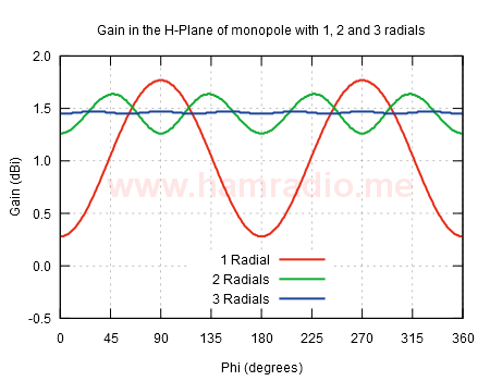
The red trace shows the case with just one radial. This is really a bent dipole with maximum radiation at a 45 degree angle. The red trace is the gain perpendicular to the vertical element resulting in the significant variation in gain caused by the tilted doughnut shape. The green trace shows the gain with another radial opposite the first. There is still a variation in gain around the azimuth, but is quite small. Surprising is the gain peaks are not inline or broadside to the radials, but are at 45 degrees. The blue trace shows the gain with three radials arranged symmetrically around the monopole. If you look close, you can see six peaks, but at this point the difference is moot.
One interesting consequence of adding still more symmetrical radials to the base of a monopole antenna is raising the capacitance between the radials and monopole. The net effect of this is each radial can now be a bit shorter in length. See “Hats, Number of Spokes, and Capacitance” and “Two Radials are Enough” in the article about the AHVD antenna for more details…
Asymmetrical Hatted Dipole Antenna
More radials also means if the energy present in one is perturbed by placing a conductor in its induction fields, the net effect is “out voted” by the numerous non-perturbed radials.
The consequence of radials
One particularly unwanted byproduct of using radials, and one that caught me by surprise when I finally figured it out, is the raising of the elevation angle. I’ve suggested above that radials contribute little to no effect on the important far-field pattern in azimuth. What about elevation. Measure any classic 1/4 wave ground plane antenna and you will see elevation on the primary lobe. Look at figure 5…

…in this web page…
Slimjim vs. traditional j pole antenna
Note the measurements (not simulations) of two monopoles (one over a metal place, the other with four radials). They both exhibit an upward tilt.
If one simulates the radial monopole with a source right on the feedpoint, but without any mast or feedline component, the far field elevation pattern looks like the classic doughnut shape you get from a standalone dipole, less a bit of gain.
So why the difference.
If you add the feedline outer conductor and/or a mast to the simulation model you wind up tilting the pattern upwards and get agreement with measurements. The problem is the radials induce currents into the mast/feedline, encourage a mast current and thus tilt the elevation pattern.
This fascinating effect is often erroneously credited to the radials somehow “reflecting” the signal upwards just like a metal sheet, but is in fact due to induced energy on the mast/feedline beneath the antenna.
This is easy to confirm in any antenna simulation tool.
Conclusion
Two or more radials shorter than a 1/4 wavelength and arranged symmetrically produce little to no effect on the circularity of the monopole azimuth far field pattern.
Radials induce energy to the mounting structure and/or feedline generating the typical up-tilt in the elevation far field pattern.

