Continuing our discussion of Single Operator Two Radio (SO2R) station design brings us to the topic of antenna routing.
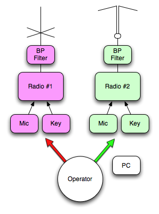
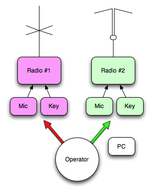
Previously we discussed SO2R gear arrangements which have two antennas connected to two radios, one antenna for each radio.
If all you have are two antennas for your two radios then there really is no point in putting in a matrix to allow either antenna to route to either radio.
However, let’s assume you do have a pressing need to multiplex the antennas and use this as an evolutionary step in our series of posts.
If we take our previous Simple SO2R station setup and add a routing matrix, we will have something like this…
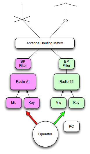
The only difference from the previous design is the “Antenna Routing Matrix” box. This box allows the vertical antenna to connect to either radio and allows the dipole to connect to either radio. In this system you would basically have a straight-through or cross-over connection. Pretty simple and pretty pointless for only two antennas with two radios.
So let’s evolve the design to include an advanced, not so simple, contest station with many choices of antennas…
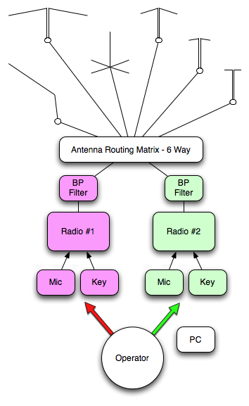
O yeah… that’s more like it. A 160 meter inverted-L, 80 meter dipole, 40 meter vertical, 20-10 meter dipoles round out the six HF contest bands. How I wish this was my station.
So what does the Antenna Routing Matrix do with the coaxial connections of our six antennas and two radios? Let’s stipulate some requirements…
- The Matrix shall allow Radio #1 to connect to any antenna.
- The Matrix shall allow Radio #2 to connect to any antenna.
- The Matrix shall prevent both radios from accessing the same antenna at the same time.
- The Matrix shall maintain RF electrical isolation between the radios.
- The Matrix shall never, ever allow one radio to transmit directly into the other no matter the excuse.
Here is one way to achieve these requirements…
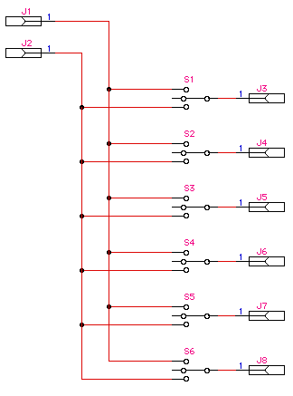
The radio RF ports connect to jacks J1 and J2. The antennas connect to jacks J3 through J8. Switches S1 through S6 allow any antenna to connect to either radio. Note how the topology prevents the radios from ever connecting to each other so long as the antenna ports are never connected to each other.
One problem with this design is the need for center off switches. Otherwise all antennas will be connected to the radios in some combination. If you want to use relays, one way around the center off requirement is to put another switch between each switch and the antenna port. Since most relays do not come with a center off option, this additional antenna isolation switch is a necessity.
Another common method adds two 1 x 6 switches like so…
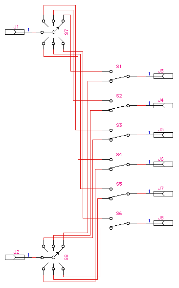
Switches S7 and S8 assign each radio to a particular antenna. The antenna switches S1 through S6 select which radio to connect to the antenna. Again neither radio can transmit into the other by accident; Even if both 1 x 6 radio switches select the same antenna, the antenna 1 x 2 switch selects one or the other, never both.
This is the method used in a few commercial products. Some products contain the whole 2 x 6 matrix. One product is a whopping 2 x 10 matrix. Still other products are piecemeal 1 x 2 and 1 x 6 switches leaving you to connect them with coax; As you can see this design requires a lot of coaxial connections, but many people do it this way.
The added bonus of the “more sophisticated” approach is the increased isolation between the two radios. Instead of one switch contact, there can by up to two open switches and one contact gap between the radios. This adds up to an incredible amount of separation between the radios made even better by the band-pass filters.
Available products include:
- Array Solutions Sixpak – Nice 2 x 6 coax switch with separate control head – $450
- Microham Double Six Switch – Indoor/Outdoor 2 x 6 coax switch – No manual control box option, expects connection to other products – $649
- Microham Double Ten Switch – Indoor/Outdoor 2 x 10 coax switch! – No manual control box option, expects connection to other products – $969
- Top Ten Devices Six Way Antenna Relay Box – Indoor/Outdoor(with drip enclosure) 1 x 6 coax switch usable as part of your 2 x 6 system per second schematic above – No manual control box option, uses control signals (from their band decoder for example) – $125
- Top Ten Devices A/B Station Selector – Indoor 1 x 2 coax switch usable as part of your 2 x 6 system per second schematic above – product designed to maximize isolation between ports, > 80dB – $77 or $390 for six
The above products have been available for some time. The contester crowd seems to use them often for their SO2R and multi-multi setups.
Conclusion
When you are ready to make a big leap forward in your contest station with ever more band-dedicated antennas, the above switching gear is what you will need to help implement SO2R.
In the next SO2R post, we will talk about the operator interfaces: microphone, morse keys, and computers.
