My search for a portable hf antenna led me to details on the vertical dipole. More specifically the…
…ASYmmetrical HATed Vertical Dipole…
…or AHVD for short. This name honors LB Cebik who first coined the phrase, but where I added the word “Vertical” to apply it to my goals. This post documents the beginning of a journey that began while researching a portable upper-HF (20-10m) antenna for Field Day 2013 as well as portable operation at lighthouses, beaches, camping, etc.
It continues with real data from my prototype design assembly built from DX Engineering components plus one readily available speaker stand.
It ends with some real-world testing at Field Day, my yard and Hatteras Island.
Please note, I am not the designer of the AHVD concept. As you will see below, the AHVD design has been around since at least 1997. I did design a variant of the AHVD to use for testing. If you want to build one right now, skip this post and proceed to Build the AHVD. If you like antenna design history (and who doesn’t right!) read on.
Let’s get into the details by first examining…
Symmetrical Hatted Vertical Dipoles
The best place to start explaining Symmetrical Hatted Dipoles is to examine the current commercial offerings. TransWorld Antennas [1] makes a portable unit. Visit the web site for clear photos.
L.B. Cebik’s articles provide some of the earliest references I could find of both symmetrical and asymmetrical hatted dipoles design concepts [2][3][4][5].
Look in the references for more examples of the symmetrical hatted dipole [13][14][15].
Asymmetrical Hatted Dipole
Cebik eventually drifts from symmetrical to asymmetrical hatted dipoles in his “Planes in Space” article[6]. The definition is, obviously, any hatted dipole that isn’t physically balanced. One of his interesting conclusions is the quarter wave monopole with quarter wave radials is a form of hatted dipole… an asymmetrical hatted dipole. Here are Cebik’s examples…
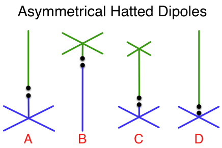
Figure 1 – Examples of Asymmetrical Hatted Dipoles
Figure 1A, 1B and 1C are various resonant structure design concepts with different feedpoint placements and hat dimensions. 1B and 1D are almost identical with the biggest difference one is upside down from the other. Cebik points out in free space, it really doesn’t matter where the hat is [6]. Figure 2D is a realization of the next design concept…
1/4 Wave radials are the spokes of a capacitive hat!
In 1997 Cebik introduced the design concept the good old quarter wave monopole antenna with radials is a form of hatted dipole [4][6] with key points shown in Figure 2.
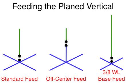
Figure 2 – Feeding the Planed Vertical
The Standard Feed in Figure 2 is the traditional 1/4 wave monopole with 1/4 wave radials. This, Cebik asserts, is merely a half-wave dipole with one half in the form of a hat and upside down. Note the feedpoint is at the intersection of the two “halves” where we usually think it should be. Antenna books teach us the feedpoint impedance is around 20-40 ohms in this configuration depending on height above ground and closes on 20-23 ohms as you move away from ground [18].
We want 50 ohms though right? Antenna designers know tilting the radials down will help bring the feedpoint to 50 ohms [20]. Cebik suggests another way in his comment…
As viewed from the perspective of free space modeling, the planed vertical is simply a hatted dipole. With a feedpoint impedance ranging from 20-23 ohms at resonance, the hatted dipole does not present the most favorable match to 50-ohm coaxial cable. However, this problem is easily solved [if] we remember that a dipole can be fed virtually anywhere along its length. As the feedpoint is moved well away from center, a slight adjustment may be necessary to re-resonate the antenna. For our hatted [dipole], this may be done either to the main element or to the radials/hat spokes [4].
Therefore…
The Off-Center feed of Figure 2 is the exact same 1/4 wave monopole antenna, but with the feedpoint at a different spot along the antenna. Cebik’s suggestion is it doesn’t really matter where one feeds a resonant antenna so long as you handle whatever impedance it presents to your feed system. Indeed we can end feed a dipole if we can deal with the couple thousand ohm impedance… like the LNR EndFedz Antennas do quite well. In this particular case, moving the feedpoint up a bit raises the impedance to something much closer to 50 ohms.
Cebik continues…
Since we cannot easily feed all 4 radials (or 8, 16, 32, etc.) at the same time, we may simply lengthen the main element and shrink the radials until the desired point appears at the “base of the vertical [4].”
Thus…
The 3/8 WL Base Feed in Figure 2 takes the 1/4 wave monopole antenna and, rather than moving the feedpoint along the vertical element, instead adjusts the vertical and radial lengths. If you stare at the middle and right diagrams in Figure 2 long enough, you will see they both effectively achieve the same result of zeroing in on the 50 ohm ideal. It’s clear to see, though, the base feed is much easier to fabricate and to properly dress a feedline.
The 2007 issue of the ARRL Antenna Book covers this as well…
The height of the vertical does not have to be exactly [1/4 wavelength]. Other lengths may be used and the antenna may be resonated by adjusting the length of the radials [18].
…and later…
Notice also that the small increase in height raises [Feedpoint Resistance] to 51 [ohms]. This trick of increasing the height slightly to reduce the size of the elevated ground system and to increase the input resistance can be very useful [18].
Antenna developer Richard Austin says in his patent’s (4,937,558) description of feeding a traditional halfwave dipole…
It is known that the impedance of a dipole fed at its center is approximately 70 ohms and further that as the feed point is shifted away from the center, the dipole impedance increases. It is the utilization of these phenomena that the impedance match of the antenna to any feedline impedance is achievable according to the letter and spirit of the present invention [21].
In the case of the hatted dipole, the impedance starts off around 20-30 ohms thus allowing us to bring it “up to 50 ohms” with the offset feed.
Christman had this to say during his 1988 experiments comparing buried with elevated radials and researching what-if combinations of 1/4 wave and 1/8 wave monopoles and radials…
Perhaps surprisingly, the best performer of this group is a 1/4 wavelength monopole with four 1/8 wavelength radials. This configuration provides more signal strength than the other variations, and also has an input impedance closer to 50 ohm [27].
The C-Pole antenna [17] and the clothesline antenna use a similar impedance adjusting technique that appeared as early as 1940 [19].
Low-Banders know about Asymmetrical Feed
The low band crowd focuses a great deal of attention on their antennas in the never ending pursuit of greater efficiency. The asymmetrical hatted vertical dipole did not escape their search. In the 4th edition of ON4UN’s Low Band DXing Weiss has this to say about the asymmetrical vertical dipole…
Using this concept we can envisage a 3/8 [wave] vertical to be used in conjunction with, say, 1/8 [wave] long radials. A 3.75-MHz vertical designed according to these principles is shown in Fig 9-35. The combination of a 3/8 [wave] long radiator and 1/8 [wave] long radials does not require a coil to tune the antenna. The radiator length shown for a wire element whose diameter is 2 mm is 26.9 meters long. With four 10-meter long radials, the feed impedance is exactly 52 [ohms], an excellent match for 50 [ohm] feed line [25].
Efficiency is always on the mind of the low bander. To achieve this goal they avoid concentrating current and voltage into smaller areas with coils and caps [25]. The AHVD has no coils or lumped capacitance. A secondary benefit is the ability to achieve a good match to 50 ohm transmission line by appropriate wire geometry.
A Balun (aka Feedline Choke) is Essential
1/4 wave radials help reduce, but not completely eliminate, the tendency for the antenna to couple energy to the feedline and support structure [4][20][22]; This is historically known as Antenna Effect [20]. It is possible to reduce Antenna Effect using an offset feed where the radials are longer than the vertical element [20]. However, Antenna Effect is “markedly aggravated” when the radials are shortened by only a few percent [20]. Therefore the proposed antenna topology greatly aggravates feedline and mast currents. This leads to two requirements:
The antenna feedline requires a “good” 1:1 choke balun at the antenna feedpoint.
Both the vertical radiator and the horizontal radials shall be RF isolated from the support structure.
Hats, Number of Spokes, and Capacitance
Antenna design aficionados will understand the more conductive capacitive area in the hat, the smaller the hat needs to be. Cebik observed this as well [4][6]. My simulations agree.
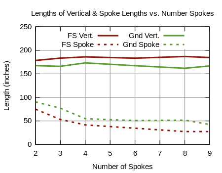
For the next two graphs I designed a 15m asymmetrical hatted dipole with a single vertical element and horizontal radials (aka “spokes”). The feedpoint is just above the point where the radials and the vertical meet. I varied the number of spokes from the minimum of 2 to 9 [8][9][10][24]. Each time I made this change I re-optimized the lengths of the vertical and radials to achieve an exact 50 ohm match. I did this in both free space and the setting where the radials are about 4 feet above average ground.
Figure 3 shows the free space results in red and the above ground case in green. The y-axis indicates the lengths of the vertical (from radial height to top) and spokes (from center to tip) in inches. In all cases we achieve a 50 ohm feed impedance.
Figure 3 – Element Length Comparisions vs. # Radial Spokes
All other things being equal we see a general trend where more radials yields shorter radial spoke length. The length of the vertical element remains steady regardless the number of radials.
This tells us the higher capacitance area with more radials effectively shortens the radial length. This is hat loading at work.
We can also tell the ground does have an effect on the antenna assembly. Some of the “are two radials enough” debates [8][16] suggest having just two radials will cause more coupling to the ground. The above graph suggests the effect of ground coupling is consistent with 2, 3, 4 or more radial spokes.
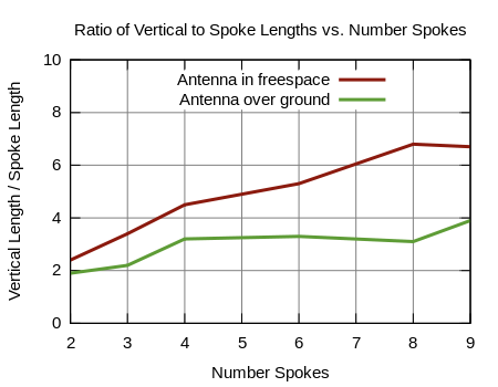
Another way to view this information is to divide the vertical element length by the radial spoke length and plot the resulting ratio. Figure 4 does just this…
Figure 4 – Element Length Ratio vs. # Radial Spokes
Note the example of 4 radials over ground has a height over spoke-length ratio of about three closely matching the above Low-Bander example of 3/8 wave height over 1/8 wave spoke-length.
This reveals we can build an antenna with shorter radial spokes if we use more of them. Whether we want to is a matter of how complex a mechanical assembly we want to tolerate.
…but…
Two Radials are Enough
So long as there is symmetry of the horizontal radials about the vertical axis, the pattern (in the far-field) is consistent or at least very similar in all directions. Cebik mentions this is his discussion about the L-Antenna…
“We could have used any number of ground plane legs greater than 1, so long as they form a symmetrical arrangement to insure cancellation of horizontally polarized radiation” [26].
Christman notes success modeling 2 radials as well saying…
To find out what impact on system effectiveness would be suffered by reducing the three-dimensional antenna system to two dimensions, I next modeled elevated-radial monopole antenna systems with only two radials. The results are shown in Tables 6 and 7. The 1/4 wavelength monopole with two 1/4 wavelength radials appears to be the best in this group, and is actually superior to the best of the four-radial “half-pints” previously described [. . .] [27].
Lastly the ARRL Antenna book suggests…
An elevated ground can take several forms. A number of wires arranged with radial symmetry around the base of the antenna is shown[. . .]. Four radials are normally used, but as few as two, or as many as eight, can be used [18].
Obviously more than 8 can be used so long as symmetry exists, but just two horizontal radials provides this electrical symmetry to a level perfectly acceptable for ordinary use.
Static Charge
If we implement the above requirements and electrically isolate the elements, we have a structure that can amass static charge. High value bleed resistors, 10 MOhm or so, between the vertical and horizontal will help. Some may see a benefit to providing a similar path to whatever you call ground in your portable operation. The final solution likely belongs on the feed/balun assembly design.
AHVD Radiation Efficiency (or lack thereof)
Nothing can change the fact this antenna design is an earth-hugger in practical operation. While the antenna itself is about as efficient as can be with no traps, coils, etc., the fact remains any antenna is only as good as the characteristics of the soil in the vicinity. Using 20m as one example, simulations reveal the following sobering points…
The 20m AHVD over a variety of typical soil conditions and range of practical portable heights offers radiation efficiency between 19% and 29%. Hurl.
The 20m AHVD over salt water raises the radiation efficiency to over 80%. Better.
It’s a lossy world. With this reality firmly in our minds, we can appreciate the following revelations of antenna gain.
AHVD Gain = ZERO! 🙁
One thing to keep in mind, this design doesn’t perform miracles with the false promise of amazing gain. Any elevated radial antenna design reduces loss in the antenna itself… and that’s a very good thing. However, ground losses in the vicinity of the antenna still exist. The following simulations show the differences between a horizontal and vertical approach.
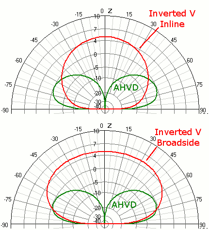
Figure 5 compares a 20m two-radial asymmetrical hatted vertical dipole (AHVD) with base 3.5 feet AGL to a 20m inverted V dipole with the peak 20 feet AGL…
Figure 5 – Vertical Dipole vs. Inverted V over Average Ground at 20m
We can see:
The simulations suggest the vertical aerial, when over average ground, has a gain of 0 dBi or so.
With vertical polarity, the takeoff angle is lower than the horizontal antenna.
Far-field ground loss is evident for both, but particularly the vertical, antenna.
The AHVD gain is uniform broadside to and inline with just two symmetrical radials confirming Laport’s suggestion to use as few as 2 radials, tuned naturally or with series inductance, in an elevated counterpoise [24].
AHVD Gain = MORE! 🙂
Oceanside
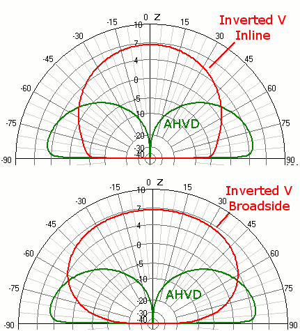
My specific goal for this antenna is to use it next to the ocean where vertical polarization yields impressively low takeoff angles and several dB more gain.
Figure 6 – Vertical Dipole vs. Inverted V over Sea Water at 20m
Vertical polarization offers an advantage for seaside low angle communications. Note the Inverted V antenna has a small vertical polarization component off the ends. This is evident when you compare the inline and broadside plots. If you use an Inverted V at the beach, orient the dipole perpendicular to the waterline to benefit from this small bonus.
Yagi Arrays
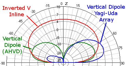
Another obvious possibility is to arrange two or more of these Asymmetrical Hatted Dipoles into Yagi-Uda arrays. The combinations are almost limitless, but with the help of simulation, many “recipes” for a parasitic array are possible. Figure 7 shows the promise of an “NBS Like” 3 element array using three vertical dipoles in the classic parasitic reflector, driver and parasitic director achieved with adjustments only to elements lengths…
Figure 7 – Comparison of Vertical Dipole Yagi Array to standalone vertical and Inverted V.
The three element vertical array in blue adds more than 4 dB over a single vertical and does so at DX favoring elevation angles. This design produces reasonable front to back as well. The azimuth plot, not shown here, shows a very wide beamwidth… typical of a vertical beam. Adding more elements quickly reaches a point of diminishing return. The point is the sky is the limit. You can have a good beam pattern with no towers or masts using many AHVD antennas with appropriate dimensions.
Commercial Asymmetrical Hatted Dipole antennas
Schiller adopts the above design ideas into his Bravo antenna line [11] and makes it available as a commercial product. He uses coil loading[24] at the feed point of his two spoke design [24][26] to shorten the element lengths for an elegant and portable assembly.
If you are looking to experiment with the asymmetrical hatted vertical dipole design right away, the Bravo series of antennas is the only commercial choice available as I write this post. It focuses on portability/pack-ability and, with the use of series inductance coils, an overall smaller antenna.
Conclusion
Schiller and his Bravo product line are reviving interest in the asymmetrical hatted vertical dipole concept. The above is meant as re-introduction of a design that dates back to at least 1997 with Cebik’s discussions using techniques from as early as WWII.
Prototype
It’s time to build something and test it. The next post in this series will focus on my prototype built with DX Engineering materials and a re-purposed speaker stand for the tripod.
“Low-Frequency Antennas,” ARRL Antenna Book. Ed. R. Dean Straw. (21st ed., pp. 6-17,18,19). New York: The ARRL, Inc., 2007. Print.
“R.F. Transmission Lines,” The Radio Amateur’s Handbook. Ed. Kenneth Warner. (18th ed., pp. 328). Concord, New Hampshire: American Radio Relay League, 1940. Print.
Smith, Woodrow, “The Offset Drooper, an Improved Ground Plane,” Ham Radio Magazine. February 1986: 43-48. Print.
Very interesting take on the ground plane antenna, I never thought of it as a capacitive hat before but doing so does clarify things in some ways. A well thought out and presented article as well. Thanks much.
Works well on 10m whilst configured for the 20m band. Tunes to about 1.5 SWR on the 28.4 frequency. Doesn't tune well when measured for 10m not sure why other than construction methods or too much aluminum. Using a 1:1 current balun. Thanks for the plans and the enjoyment of constructing it.
Thanks for the report Greg. R R on the 20m dimensions functioning on the 10m. This may not be ideal takeoff angle, but I'll have a look.
I'd like to know more about the 10m dimensions not working out so well. If you have a tunable SWR meter, do you find a higher or lower frequency where the 10m dimensions show a low SWR? I'll make sure to help you get to the bottom of this.