Super-J – As good as it gets?
The collinear J-Pole, often known as the Super-J, does improve the behavior over a regular J-Pole.
As many attest, there is an advantage when vertically combining 1/2 radiating sections to have a bit of separation between the half-wave end points.
The Super-J has very little separation between the two half-wave radiators.
Some web sites suggest the Super-J has a full 3 dB gain over the plain J-Pole which is a pretentious claim obvious to anyone with a copy of the ARRL Antenna Book and other references[1]. Indeed, the Super-J will never approach the gain advantage of a properly separated two element collinear antenna, but we can get closer to this goal.
Below you will read about how to get 0.8 dB more gain out of the trusty Super-J by replacing the traditional phasing stub with a long coil.
The Collinear J-Pole Phasing Stub
The all important phasing stub ensures the two main radiators of the Super-J are in phase. Without the stub you have a version of the erroneous 5/4 Wave J-Pole with its almost perfect cancellation of energy towards the horizon. To make the Super-J work, the conducting portion of the antenna (above the J-Feed) is made 3/2 waves long where the middle 1/2 wave is shaped to reduce it’s far-field net radiation. This leaves the two remaining radiators in-phase and contributing towards horizon coverage.
Focusing on the phase stub, we have the following possibilities in Figure 1…
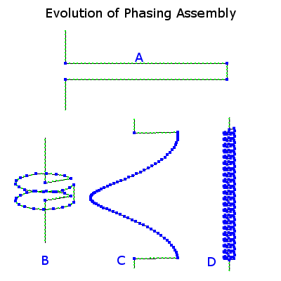
Figure 1A – Franklin Array Stub [5] – Simple 1/4 wave stub
My original version of Hiking 2m J-Pole uses a simple bent pipe phasing stub 1/2 wave in total length or about 1/4 wave “stub” length. Normal operation places equal and opposite currents on the top and bottom pieces reducing the effective radiation of the stub assembly. Simulation and practice confirm this system works quite well.
Figure 1B – Simple stub bent into circle (known as ‘Curved Stub’ from now on)
Many builders take the stub above and bend it into a tight circle around the waistline of the antenna. This reduces the stub’s protrusion markedly and yields the same performance in a visually more appealing assembly.
Not Shown – 1/2 wave of wire bent into 1 turn coil
We can take the above stub and simply wrap it once around the waistline of the antenna to provide the same phasing benefit. The “single turn inductor” provides some cancelling of this middle 1/2 radiation, but not as well as the above techniques as will be seen below.
Figure 1C – Increasing the gain with more separation
As mentioned above the best vertical collinear antennas are realized with some separation between the two 1/2 wave radiators[1]. This is the only way to approach the “perfect world” 3 dB gain of a collinear over a simple half-wave. One way to do this is to take the single 1 turn coil and stretch it to the proper separation distance.
Figure 1D – Using a multi-turn coil for the phasing component
The above 1 turn coil can reduce its diameter by increasing the number of turns. The resulting assembly is very sleek.
Figure 2 shows the above stubs as they appear in the entire antenna assembly…
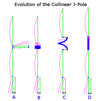
Current magnitudes are shown to reveal what proper antenna phasing looks like.
Figure 2C and Figure 2D reveal the superior separation between the two primary radiators. Quite a bit of personal EZNEC simulation went into confirming the ideal distance. The right “mechanical length” of the coil for a two element array is about 1/4 wave[1]. In the end 16 inches was “my” best compromise between additional gain and development of unwanted sidelobes of energy.
My primary goal was the antenna in Figure 2D. Figures 2A, 2B and 2C phase stubs are pretty much just a half-wave of wire bent to fit. You might think the same can be true of a 22 turn coil of wire. The problem is this coil starts to behave more like an inductor with more turns and tighter diameter.
There is nothing new about little coils on antennas. Any collinear antenna you purchase for your mobile installation has them. Cebik discusses how to properly model them in his paper “The Case of the Curly Collinear”[2].
While taking a class on antennas from Steve Best[3], I asked him about modeling coils on collinear antennas. He indicated these types of coils are part inductor and part simple wire. A perfect inductor will have constant current through its entire length. Coils like these will actually vary the current just like a straight wire. His advice was simply to model the helix shape in NEC to account for the various effects.
I did just that and modeled the coil with a fixed diameter appropriate for #12 solid copper wire wrapped around 3/4 inch PVC material.
Examining Collinear Antenna Vertical Element Separation Distance
My first task was to figure out the best vertical separation. I used EZNEC to try different vertical spacings with the goal of increasing the gain before the sidelobes get too large. Figure 3 shows some of the results…
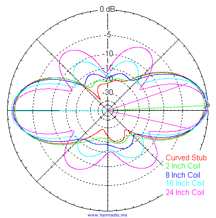
The traditional curved stub, in red, has a very nice pattern with good control over high angle elevation confirming Cebik’s findings in his J-Pole research “Some J-Poles I Have Known”[4]. The other patterns reveal the onset of sidelobes at 16 and 24 inches. In the end, I choose 16 inches as the proper compromise between gain and lobes.
One painful thing to notice in these freespace simulations is how little extra gain is available using more separation. It amounts to 0.8 dB difference. However, this does bring gain advantage over a half-wave (not shown in the graph) closer to the hopeful 3 dBd.
A 16 inch coil made by wrapping 22 turns of #12 solid bare copper wire around a piece of 3/4 inch PVC was the best answer. However, let’s explore the design space a bit. Let’s see what happens to the antenna pattern if we keep the same 16 inch spacing, but trade between coil diameter and number of turns.
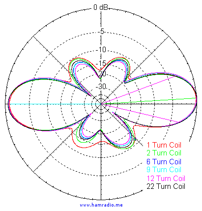
The single turn coil provides the least amount of “middle half-wave” radiation mitigation so you can see some side lobes. This improves quickly with 2 or more turns. For all practical purposes, the pattern for all coil-turns is identical. This NEC simulation tells us the pattern is controlled almost entirely by the separation distance no matter how you manufacture the phasing coil.
Comparison of “Coil-Super-J” to the Super J-Pole Antenna
Figure 5 compares four items:
- Our final design with 22 turn coil wrapped around 3/4 inch PVC,
- The 16 inch collinear with a 1 turn coil,
- The Super-J-Pole with the curved stub,
- Traditional J-Pole
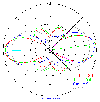
The 22 Turn Coil Collinear shows about 2.6 dB over the half-wave regular J-Pole. The traditional Super-J shows 1.8 dB.
Wire length in Collinear J-Pole Phasing Coil
Many think the wire length in the coil should be exactly 1/2 wave long. However, it took about 80 inches of wire to make the 22 turn coil. This is about 1 full wavelength of wire. I had to double check the currents along the segments in NEC to be sure I wasn’t fitting a full wave in the coil. I wasn’t.
The following table lists the resulting coil lengths after optimizing each coil design to achieve resonance.
| # Turns | Diameter | Conductor Length |
|---|---|---|
| 1 | 11″ | 37.5″ |
| 2 | 6.5″ | 43.3″ |
| 3 | 4.75″ | 46.9″ |
| 4 | 3.875″ | 50.6″ |
| 6 | 2.875″ | 55.8″ |
| 9 | 2.125″ | 60.9″ |
| 12 | 1.75″ | 66.3″ |
| 22 | 1.143″ | 79.0″ |
Table 1 – Phasing Coil Parameters
As the coil behaves more like an inductor the magnetic fields retard the changes in currents thereby forcing the actual length of wire longer for the same total phase change.
The following graph illustrates how wire length changes with coil dimensions.
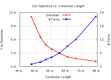
Despite the extra wire, all the coils above are 1/2 wave in “electrical length.”
Results during the AT Golden Packet
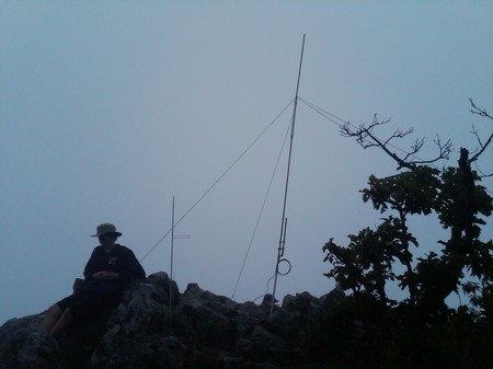
With no time for testing, we took the Hiking Super-J to Stony Man in Shenandoah National Park for the ATGP event. We brought the new phasing coil along with the older stub in case it didn’t tune up or hear signals. The good news it did tune up and it did hear quite well. We got the same good APRS signal reports as the previous years. This, however, is not much of a test since mountain top to mountain top, despite the 100 mile distance, is just not that difficult. All the signals were S6 or better.
I think you will agree the coil collinear J-Pole is more sleek than the my traditional ugly-stub version used on previous ATGP outings.
Real measured results of the Collinear J-Pole
NEC simulation, when used correctly, is a proven tool for antenna design. However, real measurements certainly give the designer more comfort.
I had good fortune to test this new antenna configuration using a real measurement system. I tested the Hiking J-Pole in both the old and new configurations. The base of the J was about 18 inches above ground. I also tested a simple three radial quarter wave mono-pole for reference with its feedpoint 48 inches above the floor.
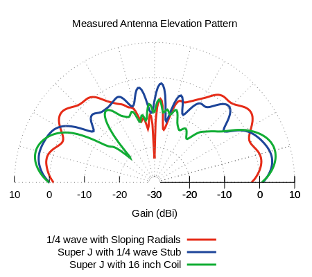
The Hiking Super-J using the coil is certainly the best of the three antennas. Both Super-J configurations beat the Monopole handily. Since there is a real “ground” in this test environment, the taller Collinear J has a clear advantage.
The Coil
Here is the coil made with #12 solid copper wire wrapped 22 times around 3/4 inch PVC resulting in a coil diameter a bit over 1 inch.
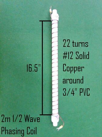
My target length was 16 inches, but wound up being 16.5 because of measurement creep. 2m is pretty forgiving of errors this small. Figure 10 shows how the wire is secured.
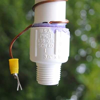
This coil should work as the phasing stub in any 2m collinear antenna, but I can only vouch for the one I made. Dimensions for the entire antenna are forthcoming.
One thing to keep in mind is this coil should be the thing you adjust when bringing the antenna into resonance. I used this approach in NEC and came out alright. If you insert your coil into your collinear project and the tuning changes, check if your are too high or low in frequency and remake the coil longer or shorter (electrically not mechanically) respectively by changing the number of turns across the 16 inches.
Observations of the Collinear J-Pole
Using a small diameter coil for proper phasing and spacing of collinear elements in the Super-J rewards the builder with higher gain and relatively sleek look. Any version of the Super-J will be quite a bit better than a standard J-Pole or simple mono-pole. However, at 2.6 dBd this new version gets tantalizingly close to the theoretical 3 dB over a half-wave goal.
Phasing stubs are always cumbersome and the coil does a fine job making this a simpler mechanical assembly. As the coil is wound around PVC, the entire antenna can be made from home center components with ease.
Designing the coil is not at all straightforward using traditional inductor calculation techniques. I used NEC to design the one above and it was spot on target. EZNEC or any electro-magnetic design tool is essential for proper design of phasing coils. Otherwise the only method left is trial and error prototypes.
Conclusion
Improvements to the Super-J are possible and practical by replacing the phasing stub with a phasing coil of proper length. Simulation, testing and real measurement reward the builder with gain better than maverick J-pole designs such as the well meaning, but lackluster Collinear 5/8ths wave j-pole.
What should we call this new configuration?
- Coil Super-J?
- Collinear J-Pole
- Ultra-J?
Anyone… Anyone?
For now “Collinear J-Pole Antenna” makes sense.
References
- “Stacking Broadside Collinear” – Charles Rauch (W8JI)
- “The Case of the Curly Collinear” – L. B. Cebik
- Steven Best – Antenna Instructor
- “Some J-Poles That I have Known – Part 4” – L. B. Cebik
- Johnson, Richard C. and Henry Jasik (1961-1984). Antenna Engineering Handbook
. (2nd ed., pp. 27-14). New York: McGraw-Hill.
Hello John,
today I fount your post about improving the Super-J antenna, wow it is so interesting, I wanna try it. May I ask you for help please? Because I am from Bulgaria /LZ1MAK or KC2YZL/, here in Europe we use metric system, so I can find 20mm PVC pipe for the coil, it is close to 3/4 inch but it is still larger. May you help me with the calculations please? How can I resize the coil? And of course can I use smaller diameter PVC pipe for the coil? If it is possible I can try to make 2, 3 or 4 elements Super-Super-J antenna, why not for 435MHz too. I am so good with the computers software. I hope you will get this comment, please send me your opinion, my e-mail is: kc2yzl@yahoo.com
Thank you, I am so exited to try something new
Hi Marin.
Please provide measurements of the wire and 20mm PVC outer diameter and I will calculate the number of turns.
John
Hi John,
thank you for the reply. For the coil is easy to use 1mm wire, PVC outer diameter is 20mm. Is it OK for 145MHz.
We can try multi elements for 432MHz, let say 10mm PVC diameter and again 1mm wire for the coil. Thank you
Marin,
For a 1mm diameter wire wrapped around a 20mm diameter PVC 406mm (16 inches) long, I predict about 31 turns are necessary for 146 MHz.
As for 432 MHz, I will need to work that out a bit, but will add it to my queue.
If you try the 31 turn solution, please let us know how it works out.
John
Add me to the list of people that would love to see this modeled for the 70 cm band. The combination of your design with Eikland and Larson's "Copper Pipe J-Pole Antennas" would be just amazing on 70m.
This is very nice post I am going to try this method of building the Super J Antenna.
the only gain you get is from the height
theres a loss from the coil
If by "height" you mean "collinear antenna height" due to the overall separation between the two radiating elements, you are correct.
The loss of the compact 22 turn coil is a good point. For those worried about it, use a larger diameter coil with fewer turns and shorter conductor length as shown in Table 1. Note, however, fewer turns mean larger changes in frequency should you need to tune the antenna by adding or removing a turn.
Copper shielding foil strip is a nice material now, instead of wire to make your coil and lower R
Hi,
J-pole is my favour vertical. I've made J-poles for 2m, 6m and 10m. Works fine for me. I wonder if additional 1/2-wave section with "separation" coil can be added without any modification to the existing antennas?
I would love to add these 2,6dB to my 6m vertical but I'm afraid about the coil mechanical length and weight.
Regards,
Bart
Yes I think you can add to your current antenna. I would make the coil form the correct length to get the proper separation between the current antenna and the new top 1/2 wave element. Then use trial and error to change the number of turns around the coil until it tunes.
Note I have found adding the extra element tends to change the resonant impedance a bit at the feed. Perhaps it won't for you, but don't be surprised if it does.
Hi, everybody. Well, I made this antenna for 220mhz and it is working very, very nice.
Thank you very much, John. Sílvio-PP7BNY
Silvio,
Could you share the dimensions and materials used for your 220 MHz version? Perhaps it is time to begin collecting the details from builders like you.
John
Silvio, I want to build this antenna for 220 Mhz. as well. Could you post your measurements for the coil here please. Enter text right here!
Have you seen http://www.hamuniverse.com/wb3ayw2mcollinear.html he gets the same results as with a 8" wire over a 1-1/2 in length.
I like it. The drawing showing the 32 turns on the 20-1/4 inch coil makes perfect sense. I'm not understanding the "3 turns over 1-1/2 inch" part however. Something like 13 turns might be about right by interpolating my results in Table 1.
Regardless, this WB3AYW multi-collinear follows good solid antenna design and should work pretty well so long as you keep it vertical. Thanks for sharing the link.
John
I have built a 30 element for 440 and the gain is great but if there is some wind the pattern shifts too much, about 15 vertical elements is about all you will want to go.
Two meters built for 146. will work on 446. also. VSWR will be under 2 to 1 on both bands which the transceivers built today will handle. A 10 element of my newer design with shorter coils as shown on the internet under ham universe website works great.
Thanks for the post Leonard. In lieu of your many comments you have sent here, I will simply suggest for everyone to look to your website for details on your design.
http://www.hamuniverse.com/wb3ayw2mcollinear.html
NOT MY WEBSITE ! there is things I would like to add to your site that is not on hamuniverse.
Leonard Shick wb3ayw
The coil has capacitance also everyone forgets about it, the spacing of the coil 1 1/2 inches and the coil diameter, do not forget the coil wire back thrugh the form is also part of the coil wire. by changing the spacing 1/8 inch you can change the frequency putting up tilt or down tilt in the antenna, the spread sheet can be used for any vhf or uhf frequency and the hole spacing for the coil changes with the frequency put in the formula.
The big coil 32 turns is the old design and the 1.5 inches is the new design and the three turns is between the wires where they come thru the CPVC pipe, do not use PVC as it has impurities in it CPVC does not. 1/2 inch CPVC is 5/8 inch outside diameter.
If using 5/8 wave radiators after 3 elements the radiation pattern goes astray.
Using 1/2 wave elements you can go as long as you want to but I recommend not to go over 15 elements in length as the radiation pattern gets too flat.
So any questions e mail me See QRZ it has my e mail as well as my phone number.
Leonard Shick wb3ayw
These comet are for two meters by inserting new frequencies in box all measurements will change except the coil diameter. It stays the same for all. By changing the coil length you can put up tilt or down tilt in the antenna design shorting the coil puts more capacitance in the coil thus lowering the resonate frequency of the coil putting a different tilt in to the design, as lengthen the stub would do putting down tilt in the design. As like a repeater antenna would need on a mountain top..
The top element is the only one with end effect, all other elements are full length.kd0pgm go to ham universe and down load the spreadsheet and out 446 in the box and hit enter
you now have your 440 design, You can also e mail me for the spread sheet.
Remember to use CPVC not pvc as the pvc is mostly not invisible to RF.
The coil spacing I use is for convince for full or half turns of #14 solid wire to be resonate, if you use different diameter CPVC the turns and spacing will be different.
Coil length for 224.00 is 13.7 inches long between holes with 49.75 inches of wire wound on coil. 48.75 inches of wire gives you down tilt for on top of a mountain.
Radiator length is 24.5 inches for top element only with end effect, all others are 25 inches between the coils. This is my old design.
On 446.00 coil spacing for new design is 1 1/8 inches with 2 turns in between the end wires thru the CPVC tubing. Element lengths are around 12.6 inches between the coils with end effect on top element slightly shorter see spread sheet.
not for publication !!!!!!!!!!!!!!!!!!!!!!!!!
Need e mail address to send you the working spread sheet/
Leonard wb3ayw
spread sheet, has box to check to change to metric and back, so all can use it !
Coils for the different bands follows.
Two Meters
Three turns in between the two end wires spaced 1.5 inches apart will set radiation at the horizon.. Insulation left on the coil wires!
Changing the drilled hole spacing by -1/4 inch will put down tilt in the design without changing the radiator, or spacing the holes at 1.25 inches instead of 1.5 inches.
.
All of my coils use 1/2 inch CPVC not pvc, it is 5/8 inch outside diameter!
CPVC does not have the impurities in the plastic.
On the 440 design the insulation is removed and the holes are drilled at 1 1/8 inches apart. with 2 turns between the end wire puts the radiation at the horizon.
By decreasing the spacing to 1 inch puts down tilt on the design.
On 220 the spacing is one inch with either 2 or 3 turns and with or without insulation
These smaller coils are Not fully designed yet as 220 band is not that popular in my area.
The design with the larger coil for 220 has the insulation still on the wire.
website off air so need them here
Hi John
Could you measure your coil wire and coil form in mm and E-mail it for me please.I would like to make the form out of a non conductive material.What is the diamentions of your lower and upper elements and the stub in mm.
Thanks
Kobus
Kobus,
I need to just go ahead and generate a fully dimensioned drawing. I will get to that soonest.
Kobus, send me an e mail and I will send you my spreadsheet.__Leonard Shick wb3ayw@zoominternet.net
220 coil over one inch wind 2 turns between the two end wires or 4 turns total,
This is on the cpvc tubing with a 5/8 inch diameter.
coil wire holes are drilled one inch apart with a drill press, being careful as to drill the holes in the center of the cpvc tubing! wind wire with 2 turns in between the two end wires. No insulation on the coil wires! This is for the 222 band only. Any other coils E Mail me address is correct on QRZ !
Leonard Shick wb3ayw
Hello John.
Joe here, in Namibia.
I wonder if you could clarify for me please – you modelled a coil ending up 3/4inch diameter, with 22 turns over 16 inch length, with No12 wire. I have tried the same, and obtain similar results, give or take a little, but your recommendation of 31 turns on a 20mm former with 1mm wire seems out. 3/4 inch is 19mm , No12 wire is very close to 2mm, so in fact wire centres when wound, for the 3/4 – No12 wire are 21mm , as is the 20mm former with 1mm wire. Why would your coil have 22 turns while the the other require 31 turns? I am assuming the frequency for both is 145MHz…Or is this a problem of AWG vers SWG vers 'No' sizes vers mm …..
Regards
Joe V51NC / ZS6JGN
Joe, I will have to revisit my answer on this. Thanks for point it out.
John,
Could you provide the EZNEC file?
The sleek version would work better on the tower up here in N.Idaho due to ice/wind. And I want the extra gain because the qth is on top of a 3000 ft mountain w/folks in the valley.
I would share the final design/construction info on the final antenna I am building for a GMRS licensed repeater!
73'
Ken
WB4ENE
US8350769
US8725214
US7084835
Hi John!
I want a build a collinear j pole for 1090 Mhz for ADS-B (receiving only).
I want to use 1 mm (18 AWG) or 1.5 mm dia (14 AWG) or 2mm dia (12 AWG) solid copper wire from electrical cables to make this antenna. The wavelength at this frequency being small (275 mm /10.8 inches) this thin wire should be ok. I want to fit the finished antenna inside a 3/4 inch PVC pipe, cap both ends with N connector at bottom cap, so that I can mount it on roof.
I will appreciate if you provide me with dimensions of all elements & coil of this antenna. Thanks.
Thanks for sharing this work. I am on board with your phasing coil approach. I have two questions about the antenna not related to the coil design. 1) Assuming that you're using a standard 1/4 wave J-pole matching stub, what is the spacing between the element and the stub? and 2) Did you compensate for the velocity factor of the PVC pipe radome/jacket in calculating element lengths?
Hi David.
1) I constructed the 1/4 wave matching stub as close as the plumbing pieces allow. What I will do soon is provide a complete drawing showing all measurements. I've been hesitant doing this I can't say this is a perfect design, but it is close.
2) No, but I did worry about it a bit… actually a lot until field tests and then chamber measurements validated the design of the loading coil and its phasing. All other elements are bare copper.
Understood. I will likely be building mine of 14 AWG stranded PTFE-insulated wire, encased in PVC pipe, except for the coil which will be eternal to the pipe. (I have most materials already on-hand.) I will use the .81 velocity factor of PVC for calculating element and stub lengths. Thanks again, and I'll post results when I get it on the air.
Hello John, This week I have built my very first J-Pole antennas using 450 OHM Ladder Line. Today I saw this article and have built a (crude) coil and top radiator to add to my J-pole. I used 12 AWG THHN solid copper coated wire. I think I have it dialed-in as best I could, getting around 2.0 SWR near the target 146 MHZ. will be testing this weekend to see how it works.
thanks for your detail explanation and instructions.
Excuse me for being so late to the party and being such a beginner….
I note that the 1 inch coil need 79” of wire. It is about 1/4 wavelength physically but 1/2 wavelength electrically. Maybe I am wrong but this seems to be impossible and I wonder if it is actually 1-1/2 wavelengths long? (It seems that the propagation through that much copper would account for a fully wavelength)
Tom
The propagation is "altered" by the inductance of the coiling such that one needs more actual wire for a given electrical phase length when coil turns move closer to each other. That's one reason I made figure 6 to highlight this interesting find. It's another good reason to use NEC, if you can, to model the coil along with the antenna as it does a good job.
John:
Thanks very much for the reply!
Sorry, my brain needs to know the nuts an bolts of what is going on….so I must keep learning.
I am hoping the demo version of EZNEC will allow me to play with this?
I built an antenna using Ed Fongs VHF/UHF J-Pole and added Leonard Shicks 1 1/2” – 3 turn coil to add an element on top. I does tune up nicely but the radiation is abysmal. Oh well we learn more from our failures! (I guess I should ask Leonard what went wrong, but you hint that his math is way off, and I was hoping to take the easy way out) Next to try and fit a “proper” coil, wound on the same 5/8” OD PEX pipe, and still get it to fit inside 3/4 PVC, AND still being under 10’!
Thanks for your insight!
Tom
John:
Any chance you could share the NEC files?
I am new to this and seeing “files that work” would go a long way to getting the hang of this.
Thanks
Tom
Hello, I am also very late to the game here. I happen to be a totally blind ham and would like some help getting a few of these built. One for 2m, 1 for 70cm and one for GMRS. The higher frequency units would have more in series elements (probably not to exceed 5 or 6). I would certainly appreciate the help on this. my email is still good on QRZ if anyone wants to drop me a line to help out.
thanks,
Eric Oyen
n7zzt
I am interested in this too, especially for GMRS !
Where's the SWR plot?
Thanks for this John, i made a collinear super j using materials that are readily on hand. I have only a 10 feet 1/2 pvc pipe, a 1/4 diam. Copper coil and a no. 12 solid copper electrical wire.. it tuned at around 19 turns and 17 turns. But i kept the lenght of the coil at 16-. 16.5.
Karl (ve6tok)
Oh sorry my bad, the wire that i used is not 12 but no.10 electrical wire. Thats why i think it tunes at 19 and 17 turns.
its been sold as Gainmaster for CB