Question
Does the 2BCX Slim Jim antenna live up to the oft touted more gain or better takeoff angle over a traditional j-pole?
Answer
Nope.
Why?
Measurements, simulations, a college paper and Fred Judd’s own article suggest otherwise. Would you like to know more? Read on…
…but first…
“Slim Jim” – What does the name mean?
Fred Judd, G2BCX, writes…
“The name ‘Slim Jim’ stems from its slender construction (it is only 60 inches long for 2 metre operation) and the use of a J type Integrated Matching stub (JIM) that facilitates feeding the aerial at the base, thus overcoming any problem of interaction between feed and aerial.” [1]
All J-poles are slim. All J-poles have an integrated matching stub. This description aptly describes the traditional J-pole antenna quite well.
A 1936 patent by Laurance McConnell Leeds shows an unbalanced feeding method of the J-pole antenna and describes the matching stub as prior art. While referring to the element of the stub Leeds writes…
“An impedance matching section of this type is particularly well suited for connecting the transmission line to the [end of the half-wave] antenna since it has a very low impedance at its closed end and a relatively high impedance at its open end.” [1]
…and later…
“To achieve this result [. . .] the transmission line at the point where it is connected to the impedance matching section must look into an impedance which is equal to the surge impedance of the transmission line.” [1]
If the JIM moniker describes the 1/4 wave stub inherent in every J-pole antenna, one can argue the term “Slim Jim” describes J-pole antennas as they have been since or before 1936.
Judd continues to describe how the antenna works…
“How the 2BCX ‘Slim Jim’ operates
Basically it is an end-fed, vertically operated, folded dipole[. . .]” [2]
Here Judd introduces what appears to be his preferred full name “2BCX Slim Jim” and the first notional difference between a regular J and his design: An end-fed dipole vs. end-fed folded dipole. At the end of his article he states…
“Please note the name ‘2BCX Slim Jim’ is copyright and the design is exclusively that of the writer.” [2]
Ignoring the fact copyrights don’t easily apply to what he seems to want to be a short trade name and the design entered the public domain shortly after its publication by the well established prior-art conventions, Judd seems to be carefully ensuring the proper name of his antenna design is “2BCX Slim Jim.”
To summarize these thoughts, Judd tells us…
- JIM refers to balanced feeding of half-wave element by feeding a quarter-wave stub and is what any J-pole antenna uses – and has done so perhaps for many decades,
- Slim Jim, by his definition, is any half-wave dipole antenna fed with a quarter-wave stub with the feedline across a portion of the stub to find an optimal impedance – this includes the traditional J-pole, Zepp, etc.
- 2BCX Slim Jim is the proper name for the j-pole antenna using a folded dipole as the half-wave radiator.
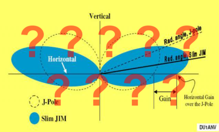
Antenna pattern measurements
Yes that’s right… real antenna measurements of each antenna in a real test chamber will help us understand the behavior of the J-pole and 2BCX Slim Jim antennas. Judd used 650 MHz models in his comparison between his 2BCX Slim Jim and a 5/8 wave antennas.[2] I compared his design to a traditional J-pole – a more apples to apples comparison. My models are proportioned for 1 GHz and made with 0.8 mm wire.

In both my models, I feed the quarter wave stub with a Folded Balun (aka Pawsey Stub) with orientation perpendicular to the antenna such that any small radiation from the feed won’t add to the polarization shown in the graph below.
Let’s have a look at an elevation cut of the traditional J-pole and the 2BCX Slim Jim antennas – note the open J stub faces left for both antennas.

Taking into account the +/- 1 dB margin of error in typical antenna chambers, we in the antenna biz call these two patterns: identical for all practical purposes.
The Slim Jim pattern maintains the classic J-pole slightly-lopsided shape with the slightly stronger and slightly higher lobe in the direction of the J stub. In other words, it does the same thing as the traditional J-pole… all the while using more construction materials 🙁
Simulations agree
Simulations reveal the 2BCX Slim Jim has never operated different than a traditional j-pole antenna. To check this more thoroughly I ran these four configurations in NEC to see the differences. Cebik did this analysis as well in his extensive body of antenna work, but those results are no longer freely available on the Internet. It took less than an hour to repeat the analysis using 4nec2.

Here we have the following antennas all trimmed and tweaked to resonate at 1 GHz using the 0.8 mm wire:
- Figure 3A – Traditional J antenna.
- Figure 3B – One element in parallel with the upper half-wave element and connecting at the bottom.
- Figure 3C – The 2BCX Slim Jim with one element parallel with the upper half-wave element and connecting at the top.
- Figure 3D – One element in parallel with the upper half-wave element and connecting at both top and bottom.
If you look close, the traditional J-pole is slightly longer than the other three. The twin wires make for a fatter conductor, wrap the length around a bit, and tends to be shorter for a given frequency… no surprise there. Now for the elevation patterns of all four antennas…

These agree well with the real j-pole and 2BCX antennas measured in a real antenna test chamber in figure 2. At this point it’s pretty crystal clear Fred Judd’s 2BCX Slim Jim antenna doesn’t offer anything special compared to a traditional J-pole antenna.
What Judd actually compared
In Judd’s defense, he never made the claim his Slim Jim design has more gain than a regular J-Pole in his article.[2] In the first paragraph he says…
“[The Slim Jim] has a radiation efficiency 50% better than a conventional ground plane due to its low angle radiation[. . .]” [2]
The “conventional ground plane” he compared to the Slim Jim is a 5/8 wave antenna of some sort. The benefits in this case were almost entirely from a beneficial take off angle, not any actual higher gain. Judd also mentions the propensity of an antenna with radials to elevate the radiation angle a bit…
With all ground plane aerials, including those with radials of more than 1/2 inch length, radiation is tilted to an average angle of 30 [degrees] or more.[2]
Indeed, my earlier measurements of two 1/4 wave monopoles, one with flat radials, the other on a large conductive sheet show this behavior…

Interestingly, simulations of the above monopole with radials do not reveal the elevated angle of radiation, rather it shows the textbook doughnut shape. However, by adding the effect of the feedline to the monopole with radials, the simulation agrees with the above measurements. Feedlines… gotta love em… gotta hate em. Note the monopole angle of radiation increase, while obvious, isn’t tragic. However, the J-pole antenna shows a slight beneficial angle of radiation because, in my opinion, J-pole users are well taught to address feedline radiation with a choke.
Some hams get it
WB6BYU concludes a very nice explanation on E-Ham…
[. . .] the Slim-JIM has no reason to work any better than a dipole, standard J-pole, or a quarter wave ground plane with sloping radials. Any variations measured among them will more likely be to differences in common mode current, to which they are all susceptible.[3]
Anyway… somewhere, somehow Judd’s published comparison morphed (likely via Chinese Whispers) from “Slim Jim & 5/8 wave” to “Slim Jim and J-pole.” The later has been copied many times on the Internet – here is one example – [UPDATE: now a dead link – click here for archive]. This has become a classic example of why the phrase “It’s on the Internet so it must be true” is bogus.
In fairness to casual antenna researchers, this myth has soaked so well into the Internet landscape, it’s hard to dig out the truth…
…even in academia…
Academic research – beware the bias
To wit check out these comments from the appropriately titled “college” paper[4] about this very topic…
Comparative Analysis of Slim Jim Antenna for Ham Radio Applications
From the abstract:
“Due to the addition of a parallel element, the Slim Jim antenna has a considerable horizontal gain over the Jpole antenna.”[4]
Sounds promising. The students setup and evaluate with HFSS a dipole, a folded dipole, a j-pole and a 2BCX Slim Jim. From their comprehensive data they summarize both the j-pole and 2BCX Slim Jim have a slight advantage over the dipoles and then subject the j-pole and 2BCX Slim Jim to a death match in their Table-5:
| Parameters | J-Pole | Slim Jim |
|---|---|---|
| Gain (dB): | 2.9040 | 3.0983 |
| Directivity (dB): | 2.9918 | 3.1355 |
dB?!? Sigh. Ignoring the lack of using dBi for the moment, the numbers reveal the 2BCX Slim Jim outperforms the J-pole in “directivity” by 4.8% and “gain” by a whopping 6.7% or about 0.2 dB difference – 1/5th dB?!? Yee Haw! The unreported margin of error is likely +/- more than 1/5 dB; It’s certainly not +/- .0001 dB as the data presentation might have you believe. I have seen this slight increase in some of my NEC models as well, but come on, differences this low are essentially imperceptible in the real world unless you’re in the “every dB is sacred” EME fraternity.
Additionally Figures 14 and 20 in their paper give the takeoff angle advantage ever so slightly to the J-pole.
Despite all this their conclusion is…
[. . .] the Slim Jim antenna provides substantially more gain than the J-Pole antenna,[. . .] [4]
Emphasis added. Equating 0.2 dB to substantially more gain is a stretch and a bit of an outcome bias in my opinion. This may be an emerging challenge to scientific credibility…
“A key feature of science is researchers’ ability to reproduce experiments – to conduct a reality check on another group’s work by using its materials and following its methods, then comparing the results.”
“It’s a way to separate results worth building upon from those that aren’t, either because a research team was careless, overlooked something, misinterpreted data, or at worst, fabricated results.” [5]
I applaud the students for their paper confirming the J-Pole and Slim Jim have essentially the same gain and similar performance. At least their work provides another simulation confirmation (HFSS in this case) the Slim Jim DOES NOT have 3-6 dB more gain than a J-pole as some web sites advocate.
Good habits of Slim Jim users – an untold advantage
There are many reports of Slim Jim users claiming a vast improvement in their radio enjoyment with the replacement of some antenna with a Slim Jim. Pondering why this might be, let’s first examine a few habits of J-pole users in general…
- J-pole users know feedline choking is important – they may not know why, but most follow this rule so the feedline doesn’t spoil the antenna pattern. Good.
- J-pole users are wildly confused about whether to ground it or not thanks, in part, to contradictory statements in the literature. Some literature mandates the J-pole must be grounded to a mast to function as an antenna: OMG. Bad.
Then we have the Slim Jim users. Many, of course, use the ladder line variants and because those are mostly self-contained, hang from a rope, choke the feedline, and don’t have a conductive mast, they should work about as well as a dipole can. However the following good habits of the copper pipe Slim Jim users include…
- Slim Jim users know feedline choking is important – they may not know why, but most follow this rule so the feedline doesn’t spoil the antenna pattern. Good.
- Slim Jim users know mast currents are a problem – they may not know why, but most follow the rule to isolate the structure of the Slim Jim from the mount to avoid mast currents. Good.
The above points about Slim Jim users suggest, in my opinion, they have better installation instructions that should apply to all J-pole antennas. Feedline and mast currents can spoil any antenna’s pattern rather dramatically. Readers of this blog know all too well my trumpeting of mast current concerns here, here and here. Neither antenna will operate correctly if mast currents remain unchecked. It’s not a stretch to suggest Slim Jim users have the advantage merely because the various Slim Jim instructions address mast currents along with feedline currents whereas J-pole users often only properly address feedline currents.
Note to Slim Jim manufacturers
All the above suggests casual observers, and even those in academia, may not know better or draw desired conclusions contrary to their own data. You manufacturers, however, need to step up to a higher standard of quality control and vet the designs you sell.
For you copper pipe 2BCX Slim Jim manufacturers out there claiming a gain over a traditional j-pole, isn’t it time you quit revealing to the planet your obvious lack of antenna design capability? It’s well worth your while to research the product you sell. If you want to manufacturer an antenna that uses more materials than a traditional J-pole with no measurable benefit, fine, but don’t mislead your customers about nonexistent gain advantages.
This admonition does not apply to manufacturers of roll-up ladder-line variants of the 2BCX Slim Jim since the extra conductor is there anyway so connecting at the top (or bottom or both) adds little cost.
Note to J-pole and Slim Jim customers
Beware bogus claims
Beware any ham radio website, antenna vendor or antenna manufacturer making any of the following knee slapping statements:
- This Slim Jim has a freespace gain of 6 dBi (no basis in fact);
- This Slim Jim has 2-3 dB gain over a J-pole (The two antennas are end fed dipoles, no more, no less, but with a little interaction from the quarter-wave stub);
- The J or Slim Jim antenna has more than 2-3 dBd gain (mistaking dBd for dBi);
- The Slim Jim and J-Pole have different take off angles (evidence clearly shows otherwise).
These are a pretty good pass/fail litmus test of functional antenna knowledge. Some of the available products and designs have sound mechanical design, superb price point, and for as much as they have successfully rendered the classic designs, functionality as a good basic antenna. You may decide to purchase their product or make their design, but you can now do so with realistic expectations – not gain hype. I suspect your biggest benefit will derive from properly addressing common mode currents on the mount and feedline because this is an easy way to ruin any otherwise functional antenna.
Beware gain claims in dB (rather than dBi or dBd)
Any antenna manufacturer stating gain as simply dB without a relational qualifier are stating nothing really. Professionals state gain in dBi and only in freespace. Some non-professionals state gain in dBd, but this hasn’t been convention in professional antenna engineering for quite some time. Fortunately the relationship between the two is dBi = dBd + 2.15 so given one, the other may be accurately derived. If you want to look like you know what you are talking about, use only freespace gain given in dBi for non-ground-mounted antennas.
Beware gain claims over ground
Antenna manufacturers sometimes state gain over ground (often to inflate gain claims), but the variables of height, ground conductivity and dielectric properties are too varied to provide a consistent measurement. Gain in freespace is the only universal way to compare antennas. That said, it is very important to understand how an antenna will behave in a particular installation, over the local ground, on a case by case basis. This is an important part of a site study, not a way to compare antenna behavior. Both freespace gain and site-specific gain are important… just don’t confuse the two.
Beware “SWR Only” manufacturers
With few exceptions, be critical of antenna manufacturers that don’t publish freespace simulations or chamber measurements of their products. Most “SWR Only” manufacturers, have stellar intent, but are running blind as to actual antenna behavior; There are some who seem to have “the knack,” but these are exceptions.
Beware hand drawn antenna patterns
Question: What’s worse than no antenna patterns for an antenna product?
Answer: Hand drawn antenna patterns for an antenna product.
If any antenna web site, but especially manufacturer’s sites, generate antenna patterns by hand (using a computer drawing package for example), know they are expressing what they “think” or “expect” an antenna pattern to be, not necessarily what the pattern is – Hurl. My watch says this is the 21st century. Unless you’re Lindenblad or Hoverman’s ghost, the practically free NEC tools and other not so free FDTD, etc. tools are the only acceptable methods to critique an antenna’s performance. The college students mentioned above use simulation… so should a manufacturer. Sure these tools have their quirks, but there are just too many variables to track. These tools track them all effortlessly.
So… if you visit a web site and an antenna pattern reminds you of the colorform fun of your youth, or looks like this, or this, the chances of sufficient technical literacy in the surrounding text are questionable. Move on.
Just say no to juvenile antenna analysis.
My list
Here is my list of Slim Jim makers who pass my “don’t make false claims” test:
- None at the moment 🙁
I’ll keep searching.
Conclusion
The Slim Jim antenna doesn’t provide any practical benefit over a traditional J-pole. Point by point…
- Judd’s definition of Slim, not unique – Any J-pole antenna meets Judd’s definition for Slim;
- The term JIM, not so new – Judd may have coined the “JIM” term, but is described in the 1936 patent;
- Simulations say, ‘no difference’ – The college students’ and my personal simulations confirm the Slim-Jim and Traditional J-pole antennas operate exactly the same for all practical purposes;
- Various simulation methods agree with each other – NEC (both EzNEC and 4nec2), HFSS (from the college paper) and FDTD all produce the same basic pattern for the J and Slim Jim – about 2-3 dBi.
- Measurements confirm simulations – My chamber measurements agree quite well with the simulations. There’s no question in my mind my simulations and measurements tell the same story. Therefore I have confidence the other variants in figure 3 are just as similar to a traditional J;
- Comparison kerfuffle – Judd’s choice to compare his 2BCX Slim Jim with a 5/8 wave GP, while perfectly reasonable and technically accurate, was unfortunately the perfect storm of confusion for a great many – it will be many years, if ever, before today’s mess vanishes. The college students’ conclusion conflicts with their very own data showcasing the general bafflement and outcome bias among a startling variety of otherwise skilled people;
- Waste of copper pipe – The extra parallel pipe in the 2BCX Slim Jim is material that provides no detriment, but no benefit whatsoever to antenna performance… except slightly wider bandwidth.[4] Note: Slim Jim antennas made from twinlead already have the extra wire so there is no waste;
- Perceived benefit likely mast current mitigation – It’s very easy to reduce j-pole performance simply by connecting it to a long mast. The general advice to RF isolate a 2BCX Slim Jim from its mount is superb advice for any j-pole and is a likely reason for observed improvement.
The exceptionally handy role-up ladder-line examples aside, the copper pipe 2BCX Slim Jim antenna uses more materials to accomplish the same thing as a J-pole. Why bother. You’re better off using the extra copper pipe as a mast decoupling stub in the Mast Mountable J-Pole Antenna.
As seen above, both the Slim Jim and traditional J-Pole antennas provide a measurable benefit to dipoles and monopole antennas using radials.
The J-pole and the Slim Jim achieve similar performance. Can we put this Slim Jim gain myth to rest please?
Don’t agree?
I’ve spent a good amount of time and effort to prove to myself the Slim Jim is really just a folded dipole with freespace patterns very similar or practically the same as a regular J antenna. I’ve shared the results with you in the figures above.
I would love to be proven wrong.
If you have chamber measurements or a NEC model that shows the Slim Jim has a freespace gain well beyond 3 dBi, the readers of this web site would love to see it. I will gladly share such results with the readers if you send me the report and/or model.
References
- Laurance McConnell Leeds, “Antenna System“, US Patent 2,124,424, 1936.
- Fred Judd, “‘SLIM JIM’ Two-Metre Aerial“
- WB6BYU Comment on E-ham, 2004-2013 – Slim Jim (does it really have gain)
- K. Ch. Sri Kavya, Sarat K Kotamraju and Sekuri Sukumar, 2014 – Comparative Analysis of Slim Jim Antenna for Ham Radio Applications
- Spotts, Pete. “An Emerging Challenge to Science’s Credibility.” The Christian Science Monitor 28 Aug. 2015. Web. 28 Aug. 2015.


my old slim jim=1/4 squire ally rod mounted on f/glass fishing rod.swr=1to1at 145.500 and 1.6 at 70cms,I havent yet tried the j pole, I ,have built a 15mm copper pipe one and works better than the ally one,the moxen does have a slight edge over the slim jim,
Do you have any suggestions for a good choke design for use with a 70cm J-Pole or slim Jim antenna?
Ferrite solutions depend on availability of ferrite material that might not be available because the frequency is so high. If you can find such material that works at UHF, a ferrite choke is the simplest approach.
The classic spooling coax into bundle does have merit and does help a bit. The interwinding capacitance is likely going to be a problem a limit effectiveness.
So long as the bandwidth is reasonably narrow, the classic choke for UHF and above is the Folded Balun (aka Pawsey Stub). They can be a bit tricky to make because the velocity factor of the area outside the coax varies enormously, but once these details are worked out, they work quite well. I discuss it here…
http://www.hamradio.me/antennas/coax-velocity-fac…
For me, it was like this….I could easily hang a slim-jim by tying a rope to the top and hoisting it up. You cannot hang a j-pole in the same manner. As far as a waste of copper; that's debatable; you can build a Slim Jim with a 10ft section of copper pipe; which is usually how you buy it in the store. Unless you've got a specific use for a foot or two of pipe…it almost seems wasteful to not use it on the antenna.
Fair enough. Your points are well taken. If the extra copper provides a mechanical benefit that's great. The key takeaway from my findings is it provides no electrical benefit… nor degradation.
I'm late to the party. Excellent article, thanks for all the info! I'm curious if there is any benefit to the extra copper on the receiving end of things? Seems like a physically larger antenna would catch more signal, but perhaps it's the same negligible difference in the real world?
Electrically there is no benefit. To obtain a benefit, the extra copper requires arranging in a way to increase the "capture area" you refer to. The classic example is a vertical collinear antenna…
http://www.hamradio.me/antennas/improving-the-sup…
The conductors in the SlimJim, while in phase, are much too close to each other to be anything more than a slightly fatter single conductor. The parallel conductors work just like a folded dipole in almost every way.
There is a serious omission amongst all this analysis . Bandwidth ! one of the most important antenna parameters .
I have not made any measurements but I suggest the slim jim standard configuration will exhibit a wider bandwidth with acceptable matching than the j pole .
I have used a j pole design for many low power special events broadcasts (VHF 87 MHz) when it equals any end fed dipole design .
I found the most successful matching technique to be with a coax balun 1:4 when all feeder interaction is eliminated , the antenna mounted on grp pole with feeder enclosed .
This arrangement seems in practice to produce very low take off angles & when used as a receiving antenna distant stations are at highest field strength with antenna completely vertical . ie. no tilt .
Russ Tollerfield
Hi Russ. Good point on the bandwidth. I did measure it and it wasn't much different, but was certainly noticeable. I will dig around for the data.
I know this is an old thread. So don't know if you are likely to respond. Your article is very interesting and obviously you put a fair bit of time and effort into this. As, I was reading, I had similar thoughts as G3SQD. If the slim JIM is a folded dipole, surely we can expect similar characteristics to the (more?) familiar centre fed folded dipole? As well as significant increased bandwidth, is the slim JIM likely to benefit from close end coupling vs. J-pole? Also, I wondered feedpoint impedance of Slim JIM vs J-pole – G3SQD mentions 1:4 balun. Not sure if a value is necessary though, maybe just sliding the feedpoint doelwn from 200 Ohm to 500 Ohm point on the J-type match would eliminate the need for the balance. So, I wondered if the above may also be factors that explain why some hams report significant improvements switching from J-pole to slim JIM. Certainly would be interested in any bandwidth data from you test. Thanks again for the article.
I tried to explain to a newly licensed Amateur that the Slim Jims secret was in its low angle of radiation rather than the published gain figures. I made no impression on the newly licensed Amateur's opinion as the Slim Jims gain figures were published on the manufacturers site, so, he thinks they must be correct. An excellent article I enjoyed it, I am now making a Slim Jim for 70mhz.
Sadly a great many makers of the Slim Jim lack the qualifications to quote antenna specifications.
I an a new ham KN4GWC, so pardon my naiveté'. Does a J-pole or Slimjim primarily radiate on lobes perpendicular to the plane of the feed loop, or parallel to it?
Excellent question. The azimuth gain around the waste of the antenna is almost perfectly uniform varying only a dB or two. It favors the direction on the side with the J stub in the plane of the J. The gain opposite and away from the stub is the lowest. The gain perpendicular to the plane of the stub is equal in both directions and is a value between the previously mentioned max and min values. Being only a dB or two apart, the difference is measurable, but hardly noticeable in practical use. For all practical purposes, it is an omnidirectional antenna.
Thank you – the current 2m setup is with a slimjim in my attic 20 feet up; with 80 watts – it gives access to repeaters 40-50 miles away. QTH is in SE Florida where most of the population is in 20 mile strips on each of the two coasts. Is there a vhf antenna that can be oriented to focus north and south, where radiation to east and west would be wasted on ocean and alligators?
In theory yes. It might be as simple as arranging two J antennas appropriately and feeding them with a splitter. There are several ways of accomplishing this. Let me put some thought into it. Which SlimJim antenna (make/model/design) are you using?
My Slimjim Made by KB9VBR – decision was based more on space than anything. Had only 59 inches of vertical space.-AND – it cost about the same as materials and time alone. Feeding it with a Yaesu 2980 via 25 feet of LMR-400 Coax. VSWR is <1.1.
Eventually want to put it outside and the 0.5 inch copper pipe is highly resistant to Florida's "fall winds".
really!
why dont you take a look at the inflated gain figures for most american made tri-banders. talk about being economical with the truth.
home-brewing antennas was quite popular in the uk, and its satisfying to make an antenna that performs as good as a commercial antenna.
i have read quite a few of fred judds articles on antennas, and he did know a thing or two.
maybe you should try using your ham equipment on air, instead of disparaging people who are trying to help others make simple antennas to get started in their ham hobby.
this "review" kinda reminds me of the old brigade who would not talk to newly licensed amateurs simply because they did not know code!
there are elitists in every hobby, but you have to remind yourself, it is a hobby!
"why dont you take a look at the inflated gain figures for most american made tri-banders. ."
Gainflation is a problem with many antenna manufacturers, be they semi-professional or amateur – This is true. Have I said otherwise?
https://www.hamradio.me/?s=gainflation
"talk about being economical with the truth"
Just being truthful with the truth.
"i have read quite a few of fred judds articles on antennas, and he did know a thing or two."
As have I. I agree he is quite knowledgeable. I've never said otherwise.
"maybe you should try using your ham equipment on air,"
Ah yes the old empirical vs. theoretical argument to invalidate any reasoning not aligning with your belief system. Did you completely ignore figure 2? While not obvious from posts here, rest assured I've used the SlimJim with great effect. One example…
http://vapn.org/news/passing-arrl-field-day-messa…
" instead of disparaging people who are trying to help others make simple antennas to get started in their ham hobby. "
Have I discouraged anyone from making their own antennas… including the SlimJim? If you think I disparaged Fred Judd then you have completely missed the point of the article. Re-read it to understand Judd's article stands the test of time. It is his choice of reference antenna that has confused so many.
If you are not one who believes the SlimJim has magical gain over a regular J, good for you. If, however, you are one who believes the SlimJim merits a significant gain figure beyond that of a regular J or dipole, you have not paid attention to Judd's own article and have simply followed the herd over the cliff of reality. Reinforcing this lie does no one, especially beginners, any good.
Excellent article, thank you. In the '80s and '90s I made quite a few antennae from Fred Judd designed and even spoke to him a few times. His dual folded dipole Yagi (I know that sounds crazy) was a very useful beam on 2m. I wish I still had all his designs!
Does the slim Jim have lower takeoff angles vs j-pole as many state which can attribute to more received energy at distances vs in a test box? Also, does the comparison change for 2m or 70cm as all the data was obtained at higher frequencies, e.g. 650mhz and 1ghz.
The answer to your question is right here in the article!
"Does the slim Jim have lower takeoff angles vs j-pole as many state which can attribute to more received energy at distances vs in a test box?"
No. Refer to figures 1 and 2 above.
"Also, does the comparison change for 2m or 70cm as all the data was obtained at higher frequencies, e.g. 650mhz and 1ghz."
So long as the antennas are built in proportion to the wavelength of the desired frequency, they result in practically identical patterns. Often the mounting structure and feedline perturb the resulting pattern greatly highlighting the need to mitigate rouge currents, but when you control for them, the patterns match.
In regards to my question about take-off angle, I should've elaborated with the two antennas suspended above the ground like have been simulated in other comparisons, e.g. 6ft 15ft and 30ft elevations. Was curious if the ground affected the lobes. Thanks for all you work!
Yes the grounds do have a profound effect on the real-world lobes from the antenna based on, more or less, the height of the antenna's center of radiation above the ground. In this example both the slimjim and traditional J have practically identical free space radiation so both will interact with the ground the same way. Generally the higher they are the more compressed the lowest radiation lobe.
That makes sense, I started thinking that after I replied above again. Thanks for all your work, really helps me learn!
For the slim jim, I'm wondering about a build-variation for the upper short: Using 1/2" copper pipe, I might try a centered, 90-degree elbow, immediately attached to two 45's, to make an inverted "V-end" (a "^-end") on the top. I'm thinking this more "graduated" electrical transition (from the parallel section) might provide an ever-so-slightly "better" short, while also providing a centered (i.e., gravitationally balanced) support-point, for a hauling-up line (like over a tree-branch). Visually aesthetic, too. At the bottom, unfortunately, I don't find any "270-45-135" copper wyes available), but one might use a tee or a cross, for symmetry there (although it pushes the parallel stub out a bit farther away). One could do the same on a lower, high-Z isolation stub. Any thoughts?
Great article and timely too, Build several SLIM JIM's over the years starting in the 1970's and whilst none of this article is news to me it does seem that a lot of misconception has crept in over the years. Fake News would be the operative word for the information that seems to surround this useful antenna.
My main reason for building the Slim Jim has always been because of slight benifits when it comes to band width and also the very easy matching stub method.
My first slim jim that I built was for use on 11 and 10 meter bands and it performed superbly though a little bit of a construction nightmare at these frequencies.
I had always thought (and still do) that SLIM stands for Stub line intergrated matching.
Once again thanks for blowing away the fog that seems to surround this radiator.
Boy there's a lot of intensity there. I still need to read through it all. However, a few points:
1. I have a lot of copper pipe lying around from a plumbing refurb, so if I can gain any benefit from the slim jim, it's the best alternative.
2. If my calculation is right, even 1dB is about 25% performance improvement: I'll take that.
3. The azimuth chart ought to compare at either's maximum elevation lobe, did you adjust the angle independently for that? Just curious, because if you didn't I would expect that would mask any gain.
4. I did not check, but another stated advantage is the SWR bandwidth, did you address that?
Thanks
Hello!
Before I tell my bit, I want to say that I know I haven't the proper gear for antenna design and build. I have only a single Power+SWR meter, Micronta (Radio Shack) catalog number 19-320. It's all I've got at the moment (in fact, it's only a loaner at that!), and I can't afford better just yet, but when I can, I will upgrade to proper gear. That said, even though a good SWR doesn't necessarily mean I have an efficient design, (1) it does imply I won't fry my finals trying, and (2) I've actually gotten some results that imply I'm doing okay.
I've built two Slim Jim antennas now, both out of #14 (AWG) THHN electrical wire. I played with the first one a bit before soldering the wire to the coax feed, and after building it I realized I could use it on both 70cm and 2m. I desoldered the coax from the wire and adjusted it about a bit more, testing SWR and comparing that and power levels on both bands before settling on one mounting for the wire to the coax. I ultimately wound up soldering the thing back together and ended up with a very acceptable 1.18:1 SWR and 4.0 watts on 2 meters and a 1.05:1 or so SWR and 3.5 watts on 70 centimeters……if that Micronta can be trusted.
Still, even if it can't be, if I had a bad SWR or bad antenna, I wouldn't expect to be able to talk to repeaters 20 miles distant on only 1.3 watts. I've had another "radio" that put out 1.45 watts and had a hard time hitting something two miles away, but I digress…
So my question is this, even though traditional J-Poles and Slim Jims perform reasonably identically on one given frequency, does the Slim Jim by any chance lend itself more to dual-banding given the extra radiating length, compared to a traditional J? Would you be willing to model that out in a NEC (I would but I haven't had the time to learn how yet), comparing a 70cm Slim and a 70cm J both on 70cm and 2m?
Kind regards, enjoyed reading the article…
A J-pole or Slim-Jim is a MEDIA WAVE antenna, which uses a 1/4 wave length of the transmission line as a coupling device, and which is NOT ANTENNA. It is a Zeppelin antenna invented before the radios and electronic valves, when transmitted and received with telegraphs to spark. This transmission and coupling line, it is the one that puts it at a disadvantage in performance with respect to a 1/4 antenna with planes, or a dipole, because they do not use that system. This lower performance as an antenna means that they are not used in commercial broadcasters "broadcastings" Greetings.
"A J-pole or Slim-Jim is a MEDIA WAVE antenna"
Never heard of "Media Wave" antenna an search turns up little.
"This transmission and coupling line, it is the one that puts it at a disadvantage in performance with respect to a 1/4 antenna with planes"
Please see figure 5.
"they are not used in commercial broadcasters broadcastings"
True. No immunity to mounting structure currents ranks high as a reason.
Okay, Technician here studying for General. I have a Slim Jim for 2 meters. I also have built a 1/4 wave antenna with 4 ground plain elements. SWR 1.2 on 1/4 wave. SWR 1.1 on Slim Jim. 25 ft of RG8X cable used on both antennas. Baofeng UV82HP at max 8 Watts used.
Repeater is 15 miles away in Downtown area.
Using the Boefeng upgraded antenna I can trigger the Repeater but I am not clear enough for a listener to make out my words. Standing on 8 ft latter.
Using the 1/4 wave I can trigger the at 20 ft in the air I can trigger the Repeater and some of my words can be heard with medium static sound.
Using the Slim Jim at 15ft above the ground I am loud and clear.
I will not argue your results or theories as I am only a Tech class and just learning. But In my situation The antenna definately delivers increased performance.
Now. That is to the east which is pretty clear. I am blocked fy forest to the south. I plan to but up my 21 ft pole and test the regular J-pole against the Slim jJm to see which gets me through or over the vegetation once I have the resources. Take off angle test. Will they be the same of one better than the other? Who knows.
Made well, the SlimJIM (or J) should have measurably better performance over the 1/4 wave. It won't be much, but some. The 1/4 wave suffers a bit of coupling to the feedline resulting in the slight uptilt in the E-Plane you often see.
What a surprise to read an interesting article and find myself being quoted!
Even if it was from nearly a decade ago, the antennas haven't changed in the meantime.
At some point I'll run some measurements on J-poles using the same two radiator wires, just connecting them up differently: shorted at top, shorted at bottom, both, or neither, along with a single radiator. I expect the differences to be insignificant, but will record the actual results on my website at PracticalAntennas.com, along with the methodology, so folks can critique it. But don't hold your breath – it may take me a couple years to get around to it.
And I'll be sure to link to this article as well.
Bandwidth? Versions with a fatter radiator, regardless of how it is connected, likely will have wider bandwidth than a single wire, so if you are building with twinlead, you can hook the the two radiator wires together, or not, at either end, with little difference, and likely similar bandwidth. That's another experiment I want to run.
The late W4RNL ran extensive models of the different forms of the J-pole in his article, "What is a Slim Jim?" http://on5au.be/content/a10/vhf/sj.html
But the conclusions shouldn't surprise anyone who has read this far.
That's not to say that the Slim-JIM is a bad antenna, by any means. But there is nothing in the design that makes it inherently any better or worse than any other half wave antenna. Sure, there are plenty of poor antenna designs out there that you can compare it too and see differences, but a well built half-wave antenna will work like a half-wave antenna. The take-away, perhaps, is that a well-built half-wave antenna can actually work quite well, regardless of the type.
– Dale WB6BYU
I have a question about the radiation pattern of the Slim Jim antenna. I see your diagram, but I didn't see a reference point as to which direction the dead spot is (and the maximum gain). Any chance you could help me out with that? Thanks, Jeff KA3RWA
Buenas tardes amigos de la,radio….alguno me podría decir si el factor de velocidad del calculador de slimjim es referente al conductor irradiante de cobarde la antena ? O e referente al coaxial de alimentación de la antena? Porque no pude conseguir el dato del factor de velocidad del aluminio en el caso que sea ese el que necesita para realizar el calculo. Gracias ; juliocchiapello@hotmail.com