My interest in radio operations away from the QTH began a search for a Portable HF Antenna. Inspired by the possibilities shown in the prior art of the asymmetrical hatted vertical dipole I decided to test the real thing. I thought long and hard about procuring a commercial offering. The price was reasonable, but, in the end, the cost of shipping put a delay on procurement timing.
What to do?
I decided to price out the aluminum for a home brew portable HF antenna. The cost savings was just enough to speed things along.
I have never once built a home-brew aluminum antenna. Readers of this blog will attest to my affection for antennas made from locally available copper. Now was as good a time as any to make this antenna the traditional way.
The major point about aluminum is the relative ease of nesting one inside the other to yield a long antenna from short components. As one of the goals of this Asymmetrical Hatted Vertical Dipole is portability, this had instant appeal.
I came up with a design and built a prototype. You can too!
DXE Catalog is the “Erector Set” for Antennas
DX Engineering makes it fun to prototype antenna ideas with their parts.
They deal with aluminum tubing in a big way. I love my 43 foot antenna from them. It was a natural first place to go for a supply of antenna components.
Pleased with my experience using the Resin Support Blocks for my Hex Beam and TV Antenna, I made sure to consider them for this project.
DX Engineering also sells rectangular plates for use in the junction points of beam antenna elements and boom. Thinking their small version was 1/4 inch aluminum plate, I added that to my wish list.
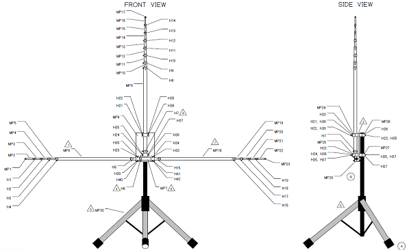
After some time with simulations and with their web catalog handy, I came up with this design…
Figure 1a – Front and side views of the vertical dipole antenna.Figure 1b – Complete drawing with parts list and assembly instructions for any band between 20 and 10 meters.
Brand new parts for this antenna assembly, including the $50 speaker stand, will set you back about $250… more than a little, less than a lot. Those with existing aluminum stock can likely reduce cost.
Tripod for the Portable HF Antenna
One major premise of this design is the use of a commercial speaker stand from the music/sound reinforcement industry. A tripod with its various angles, stress points, etc. is not an easy thing to design and make. You don’t have to because the music industry offers quite an assortment of sturdy models. Speakers are heavy things so these speaker stands already include engineering to make them plenty strong enough for this lightweight aluminum antenna and other uses. A speaker stand was a “nobrainer” for this project. Fortunately, I still have a couple stands from the “rock band” days.
With the prototype design more or less complete I made an order to DX Engineering and dug out my speaker stand. This stand, by the way, is the same make and model used in the Hoverman “Superbowl” TV Antenna.
Many speaker stands have 1-3/8 inch (~35mm) masts plus an optional plastic sleeve to accommodate speakers with 1-1/2 inch (~38mm) sockets. The key feature of my stand is the unique reversible upper section. This is 1-1/2 inches diameter for most of the length with one end narrowed to 1-3/8 for about 6 inches. This allows the stand to interface with either size speaker socket simply by flipping this upper shaft over. This is a big advantage for us because it provides a nice long 1.5 inch mast to interface with the rest of the antenna. Here is a link to the manufacturer of this stand…
Other nice features of this stand are adjustable height, up to 80 inches, and a locking pin to secure the mast. The antenna’s weight is much less than most speakers so you can rest assured the locking pin isn’t really necessary, but is there for the cautious. The adjustable height is a great feature to have for any antenna.
Shop around. Despite the news to the contrary, the economy is not in good shape and the various music equipment suppliers are in savage competition for your dollar. Amazon reveals this quite well…
You should be able to get this stand for a very good price and with little to no shipping costs.
Note, the On Stage stand is made of aluminum and will resist corrosion. However, the small hardware parts are steel and will quickly rust outside. You can replace the parts with stainless steel or coat them with something like oil, WD40 or maybe paint. I am eager to hear how others handle this.
Balun – Choke
Apologies to everyone. The absolutely essential feedline choke is not an inherent part of the antenna design. Schiller’s Bravo and this design assume you will provide this as part of the feed system.
Different folks will have different approaches to this.
When I tried my commercial DX Engineering balun, it did perform the choke function, but not as well as I desire. A good choke will force most of the currents to remain on the antenna. A great choke will force even more of the currents to remain on the antenna. When using the DXE choke, I could change the SWR measurement slightly by touching the coax. It was good, but not great.
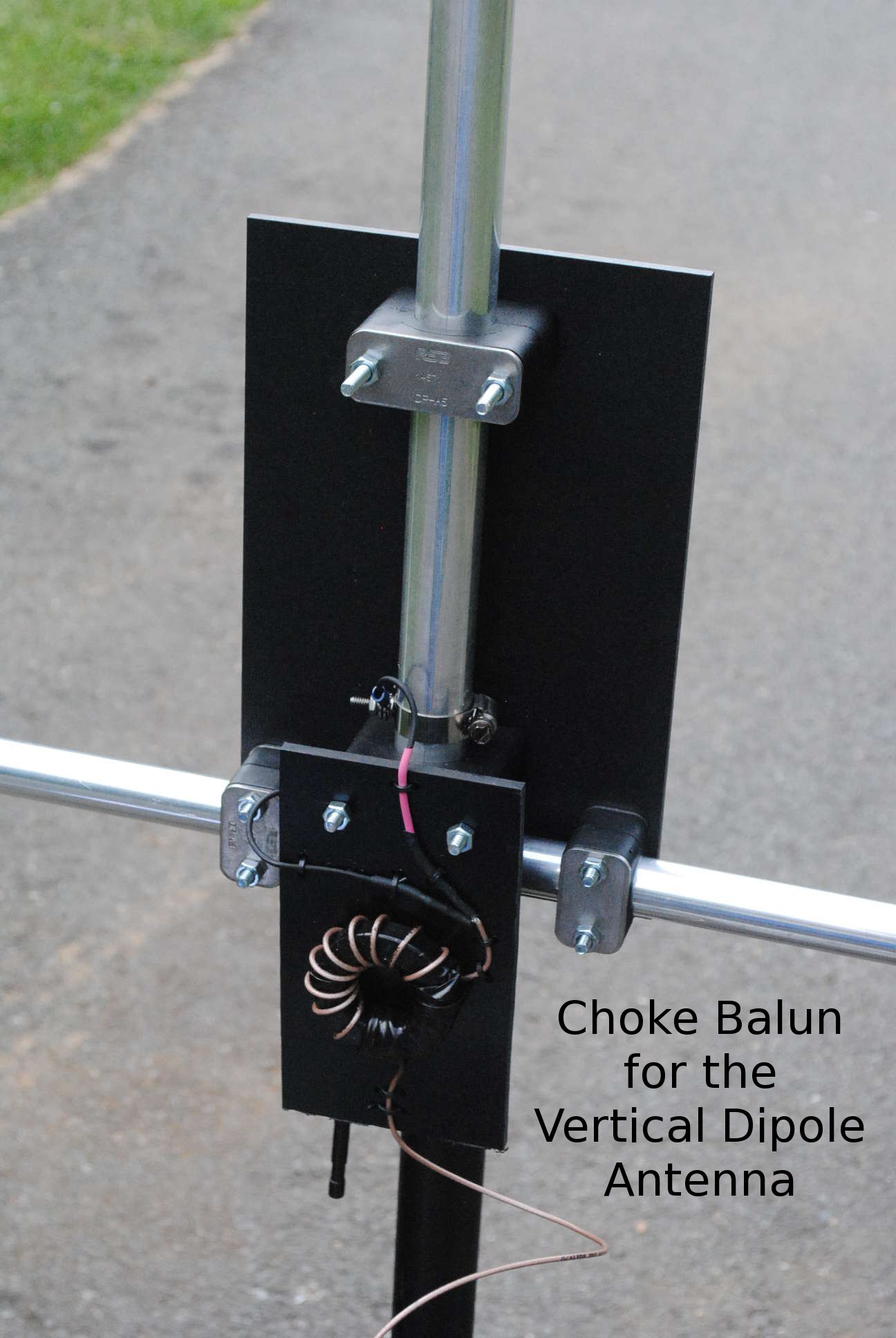
I read Jim Brown’s PDF about RFI, Ferrites and Baluns [1] and used the design guide within to design a QRP balun with a focus on very very high common mode rejection ratio. The balun you see in the photos below contains RG316 coax wrapped around a 2.4 inch Type 43 toroid. This baby chokes hard core and completely eliminates all perceptible feedline sensitivities. Thanks Jim!
I have another choke balun for higher power using RG142 coax. Following Jim’s advice once again, I used three cylindrical toroids with 3 or 4 wraps each. This yields three lower impedance chokes in series to achieve the high choke impedance goal in the upper HF range. I used this in the Field Day setup shown below with success.
So I’ve used four different choke baluns with the AHVD prototype: DXE Commercial unit, RG316 QRP toroid, the RG142 triple series and, most recently, an RG-58 100 watt toroid version. I guess my point is the choice of balun is likely a personal choice for the antenna maker.
This big subject of baluns for the AHVD deserves its own post. Expect one in the future.
Parts arrival day
When the DX Engineering order arrived I opened the package to find aluminum tubes, resin support blocks and one rectangular plate. I was very interested in the plate so I picked it up first. Wow light. Wait… this wasn’t aluminum. It’s a piece of black plastic.
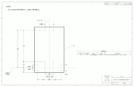
Oops… in my haste I did not read the description on DX Engineering’s web site closely. Sure enough I ordered a plastic plate. However, it was 1/4 inch thick and seems quite sturdy. After some thought I decided to use it as the back bone of the antenna. Here is the drill drawing to convert this piece for use with this antenna design…
Thinking it was 1/4 inch aluminum I was prepared for quite a drilling task. I even purchased a special bit.
DX Engineering now offers this polymer plate drilled to the specifications in the KX4O-000050 drawing above. They also now supply the 1 foot center aluminum tube with slits at both ends.
It all turned out reasonably well. Let’s have a look…
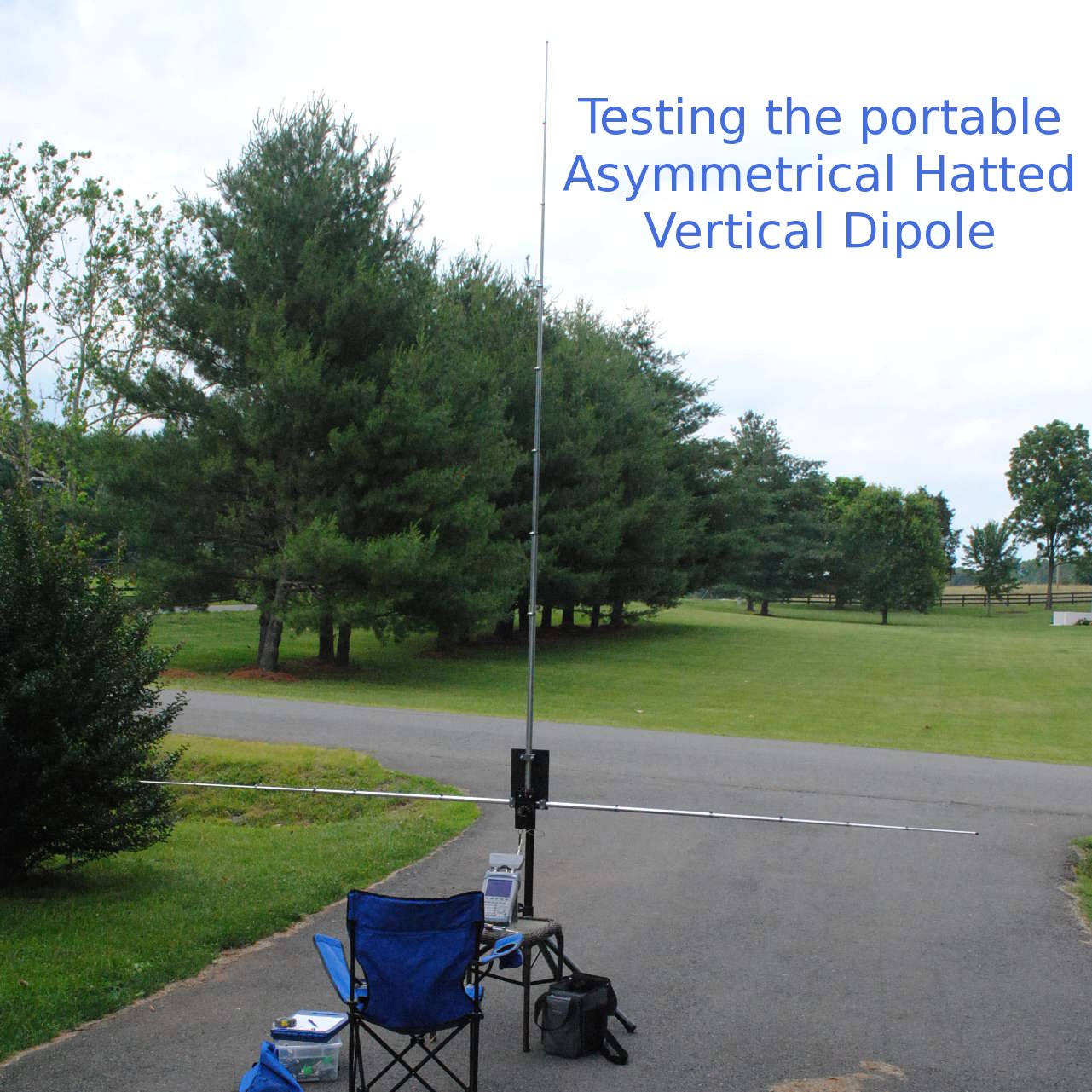
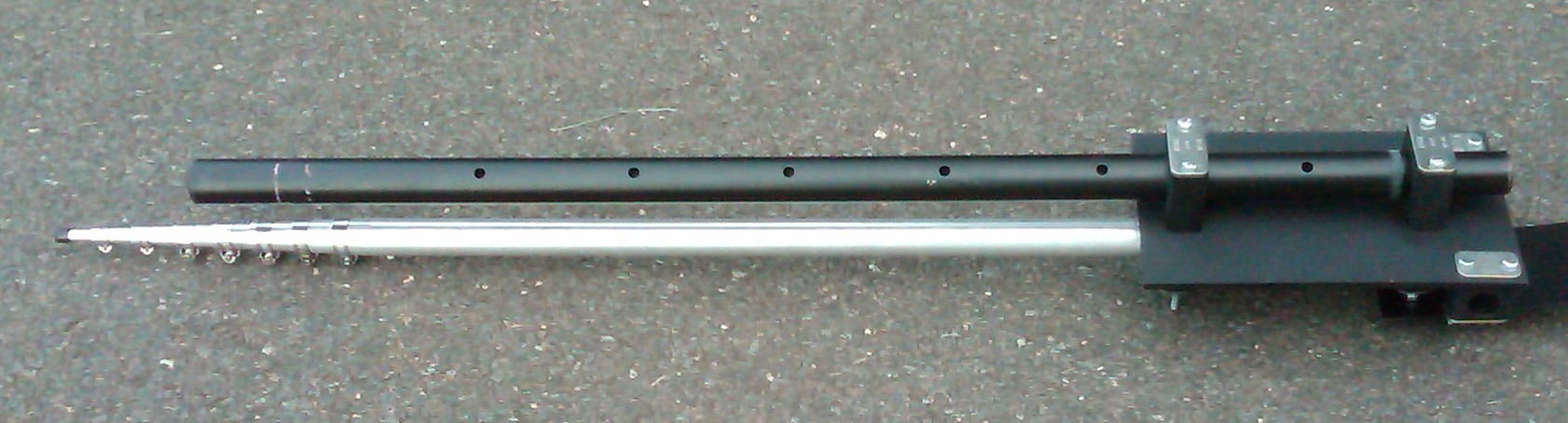
Portable HF Antenna Prototype in Driveway
The driveway became my test area.
Figure 3 – Asymmetrical Hatted Dipole Protoype
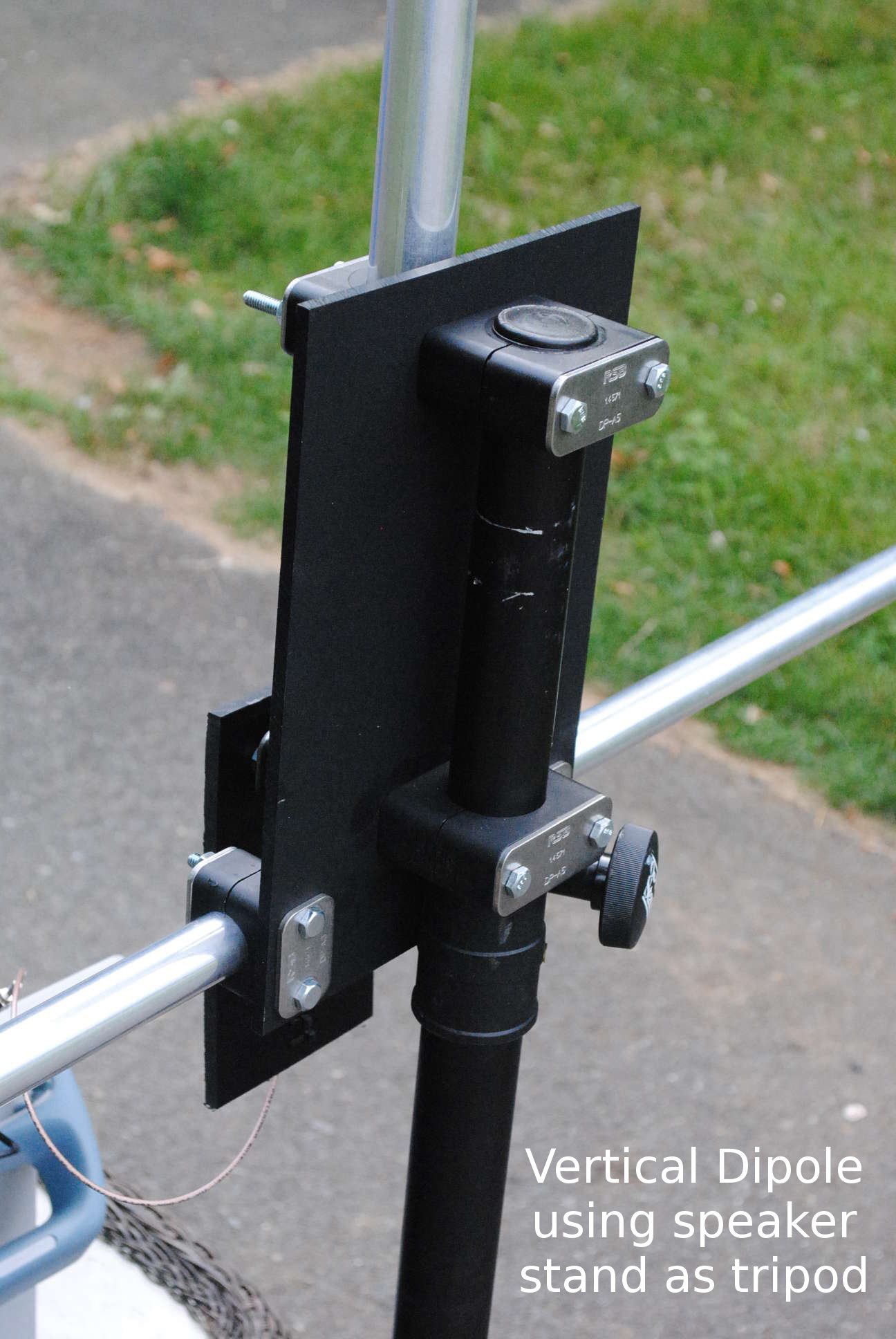
Figure 4 – Tripod side of Asymmetrical Hatted Dipole Support Plate
Figure 4 shows the tripod side. The DX Engineering resin support blocks do a fantastic job of holding on to the speaker 1.5 inch diameter stand.
Figure 5 shows the tube side of the support plate…
Figure 5 – Tube and feed side of portable HF antenna Support Plate.
Note the resin support blocks for the vertical aluminum share the 1/4-20 hardware with the tripod blocks on the other side. In this way, the support plate does not carry the load of the vertical as it transmits its load directly to the tripod mast.
Figure 5 also shows the absolutely essential balun. You need a good one as this design encourages current flow on your feedline. Drawing KX4O-000049 has some suggestions. In this particular case the RG316 balun is more than sufficient for my planned QRP operations. Note also, the lower two bolts holding the tripod and vertical aluminum serve a third purpose of feed/balun mount points.
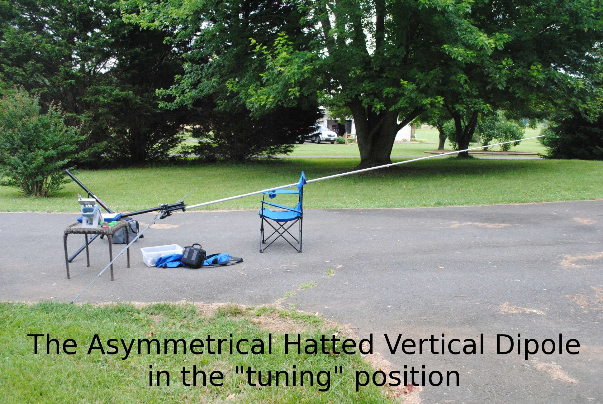
Figure 6 – Portable HF Antenna in “tuning” position
Measurements confirm this portable HF antenna has enormous bandwidth
The antenna takes some fiddling to find the 50 ohm sweet spot, but it falls right in place once found. Here are measurements for each band after experimentally adjusting the radial and vertical lengths…
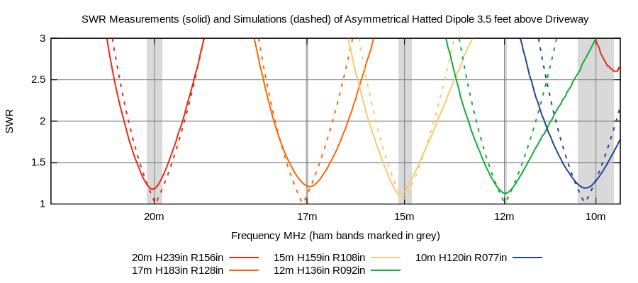
Figure 7 – SWR of Asymmetrical Hatted Dipole
Key points to know about Figure 7…
The x-axis is logarithmic.
The legend reveals the vertical height above the radial “H” and radial spoke length “R” dimensions resulting in each SWR plot. These are also in the KX4O-000049 Drawing.
The dashed lines are the SWR values from simulation for comparison.
Other tests reveal the ground does have some effect and broadens the bandwidth from 7% to about 10%. That’s clearly loss in the soil and not a surprise. These measurements were made in haste as I was marking the various tube settings with a sharpie. The good news is I could easily, very very easily, achieve close to 1:1 if I spent more time. A Return Loss of 25 dB or more is well within reach of this antenna topology.
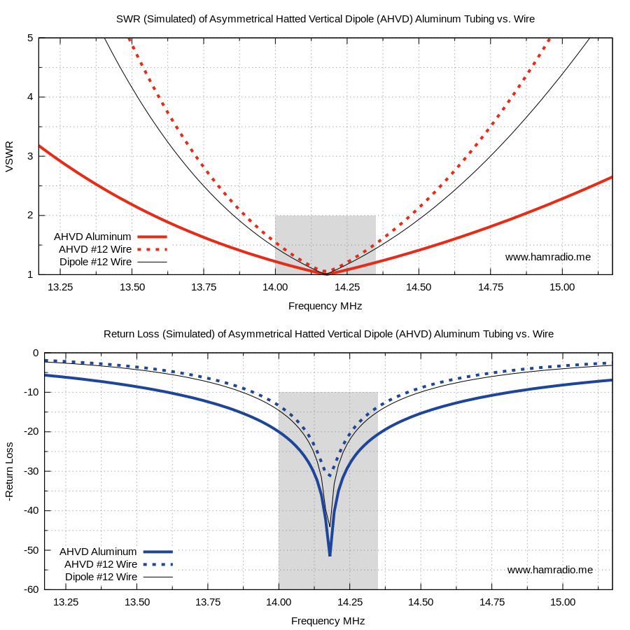
The large tubing also broadens the bandwidth as shown in this 20m view of the aluminum tube (thick solid line) vs. a simple wire (thick dashed line). The 72 ohm SWR and Return Loss of a simple resonant dipole (thin black line) is shown for comparison. Click the image for a better view.
Figure 7a – AHVD Bandwidth vs. Conductor Size
As the simulations and measurements suggest, the bandwidth is amply wide enough to cover each band handily.
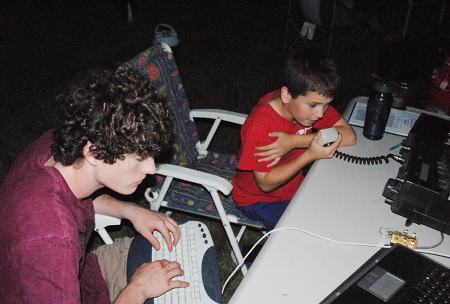
First Field Test at Field Day 2013
Where better to conduct initial field tests of a portable HF antenna than at Field Day. I was in charge of the GOTA station and made this antenna the 20m aerial.
Figure 8 – Field Day test for the Portable HF Antenna
I did replace the RG316 balun with a larger one for piece of mind at 100 watts. I also guyed the assembly with tent stakes and Dacron; The speaker stand has enough tie points to make this easy.
Did it work?
Yes it did and here is KJ4FAJ helping a youngster make 20m contacts to the West from Virginia using only this 0 dBi antenna and about 100 watts…
GOTA, 20m and the Asymmetrical Hatted Dipole
Thank you boys. You helped test two new antennas this Field Day… the other being the mastless 40m dipole.
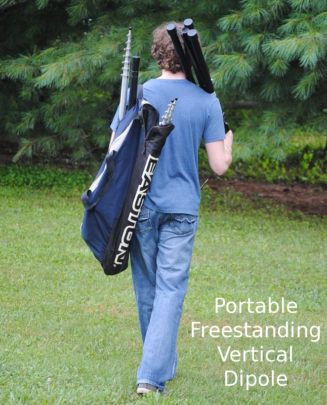
This Vertical HF antenna is portable – sort of
This picture shows how the nested aluminum tubes and the tripod extension collapse enough to fit into one of my son’s old baseball bags.
This is a portable HF antenna.
The tripod of the speaker stand won’t fit into this bag. It is very light, however, so isn’t hard to haul a great distance. Remember, the speaker stand is designed with the poor band roadie in mind.
The aluminum antenna element tubes take up less length if you don’t nest them, or by removing the clamps and nest them fully. Your choice. I leave my clamps on to make setup and break down quick. The longer vertical section is in the open end bat storage pocket.
I leave the speaker mast portion of the speaker stand on the plate, but with the mast slid up to be parallel and opposite of the vertical aluminum…
Tripod mast in the “stowed” configuration
I should note the Bravo Antennas from Schiller are more compact and portable than this prototype.
Summary
So far this antenna is a keeper. Favorite points include:
Robust – The DX Engineering components and commercial speaker stand combine to form a rock solid assembly that, other than potentially tipping over in the wind, you don’t have to worry much about.
No Fuss Design – The lack of series or shunt reactive components along with thick aluminum elements keeps the bandwidth very broad with predictable, achievable and reliable behavior. Yes, there are still interactions with the soil beneath, yes the two radials are more easily electrically perturbed than, say, nine radials, but nothing here demands critical dimensions or super tight tolerances.
No Loss Design – Additional loss from series or shunt reactive components, however small they might be, are zero in this design.
Single band AND Multi band – This is a single-band-at-a-time antenna. You must change element lengths to change bands. Clever multi-band feed designs are certainly possible with this antenna assembly. Where I have a choice, I lean towards simpler designs… less to break. I don’t mind the time it takes to change bands manually, but others might and that’s perfectly fine. Placing a tuner/matcher at the feedpoint of this antenna assembly is a viable option.
Yagi Ready – Because the elements are continuously tunable from about 13 MHz to well past 30 MHz, the prospect of arraying two or more of these assemblies, in Yagi-Uda fashion, is exciting. A future article on simulations of this antenna will explore this.
Feedpoint where you need it – The bottom feedpoint is more convenient than traditional center-fed half-wave vertical dipoles… such as the “I” styles.
Buy, Make and Take – This design’s strength is its simplicity, portability, availability and modest cost.
Another choice for you – This portable realization of the Cebik, et al., asymmetric hatted vertical dipole is a worthy alternative choice to many freestanding portable HF antennas including the “I” shape symmetrical vertical dipole and the various Buddipoles.
Potential Uses of the Asymmetrical Hatted Vertical Dipole
This is a well behaved portable HF antenna for 20m – 10m with the following potential uses…
ARRL Field Day,
Portable field work including lighthouses, IOTA, parks, special events, etc.,
Camping,
HOA restriction avoiding “Lawn” antenna,
Summits on the Air (SOTA). Yes, this might be a stretch, but certainly possible.
Conclusion
If you need a freestanding 20-10m antenna that’s easy to build, easy to tune and relatively easy to carry, this design is worth consideration.
The next posts report results of using it at the beach for some lighthouse and IOTA work.
References
Brown, J. (K9YC), “A Ham’s Guide to RFI, Ferrites, Baluns, and Audio Interfacing.” Audio Systems Group, Inc., 2010. Retrieved July 30, 2013.
Tom reliably responds to me on his canscan7 email address.
The Bravo is quite a bit more portable and “breakdownable” than the above erector set version of Cebik’s 1997 public domain concept thanks to shorter pieces and series inductive loading. The Bravo’s method of band change is pretty cool too.
If you can stomach laborious tube-clamp band changes, then the 000049 design is for you.
Please note both options require you to provide a very good feedline current choke that works on all bands of interest… unless Tom has solved that in a recent iteration of the Bravo design.
Great work! Especially with the plan. I bult a wire variant a couple of years ago. It worked superbly! I’m thinking of copying your design. Have you ever tried to load it for 40? I guess the loads would be different for the radiator and the radials? It would be interesting to hear your experience from it – if that is case.
Please copy away and let us know how it works out and if improvements are in order… especially with the currently flimsy feed/balun mechanics.
I have not loaded it on 40 yet since I have other solutions for this band, but it is certainly possible with the series loading shown by Edmund Laport (see references in the AHVD theory post just before this one). I've often wondered the outcome of putting one of the popular remote autotuners at the feedpoint. If one tames the feedline currents appropriately, this may be quite viable.
I plan on make at least 6 of these for iota 2014 for a dx-pedition to be placed near the water.
is there any chance you could post me the large full sie drawings to the uk? I feel he balun could be laced better. I'm going to construct one to take a 1kw and see if it can be placed in a box surface mount to the elements rather than hagning down.
I've since tidied up a new choke with RG58 and put it on another KX4O-000050 panel which I then mount over top the two sets of vertical mounting holes. I used this during Field Day and have photos posted.
As for large drawing, just click on the image of the drawing above to get the PDF. It is meant for large size paper, but PDF scales very well to whatever size print you want. Oh wait, by "post me" you mean mail you something right? It would be a lot cheaper to have one printed locally.
Very interesting antenna indeed and great that you have adopted it for the use of my favorite band 17m. Can a very good quality 4-1 balun be used at the feed point?
In theory yes a 4:1 balun should work, but the ratio of vertical to radial length increases to accommodate the higher impedance. Trial and error with a good VNA or even an SWR meter should help find the new antenna settings. A risk is there either isn't enough height in the vertical or enough "shortness" in the radials to accommodate the 200 ohm impedance for the end bands. 17m might work.
Ok, I;ll have to do some more investigation on the choke. Will ask the old timers down the radio club and see if they can help me construct one. I have already started work on the vertical section of the antenna and will order the radial tubes in due course.
Do you have any technical comments on N6BT's (Tom Schiller) new Evolution series antennas? For example his EV-5, five bander. The design looks very interesting, especially for those of us that live in HOA's with antenna restrictions. I do wonder about possible issues with common mode currents.
Very Interesting reading. As you're modeling pointed out the design does well to create a good match to 50 ohm feed lines. However, ground losses are still an issue. Have you done any modeling of this antenna design at higher heights? I have one of those military surplus mast systems that would allow me to easily get the base of this antenna to a height of 30 feet. Nearly 1/2 wavelength on 20M. I wonder how much more efficient that might be?
Some quick modeling suggests getting away from the earth helps, but with diminishing benefits as you get above about 6 feet or so at 20m. With less lossy ground loading the antenna the impedance of an AHVD tuned for near earth drops to 30 ohms or so. Lengthening the vertical and shortening the radials brings the impedance up to 50 ohms with the base 30 AGL. Remarkably, the gain towards the horizon improves only slightly… less than a dB or two. It helps, but not be huge leaps and bounds.
This antenna can be dual-band, such as: 10 and 12 meters, 12 and 15 meters, etc.
Simply tune it to exactly half way between the two desired frequencies. Then…
* Extend one horizontal element until you tune to the lower frequency.
* Shorten the other element until you tune to the higher frequency.


Thanks for the information on this antenna… Wanted to purchase one but its near impossible to get through to BT' Ill build it instead.
Thanks for the comment.
Tom reliably responds to me on his canscan7 email address.
The Bravo is quite a bit more portable and “breakdownable” than the above erector set version of Cebik’s 1997 public domain concept thanks to shorter pieces and series inductive loading. The Bravo’s method of band change is pretty cool too.
If you can stomach laborious tube-clamp band changes, then the 000049 design is for you.
Please note both options require you to provide a very good feedline current choke that works on all bands of interest… unless Tom has solved that in a recent iteration of the Bravo design.
Great work! Especially with the plan. I bult a wire variant a couple of years ago. It worked superbly! I’m thinking of copying your design. Have you ever tried to load it for 40? I guess the loads would be different for the radiator and the radials? It would be interesting to hear your experience from it – if that is case.
Wolf,
Thanks for the kind comments.
Please copy away and let us know how it works out and if improvements are in order… especially with the currently flimsy feed/balun mechanics.
I have not loaded it on 40 yet since I have other solutions for this band, but it is certainly possible with the series loading shown by Edmund Laport (see references in the AHVD theory post just before this one). I've often wondered the outcome of putting one of the popular remote autotuners at the feedpoint. If one tames the feedline currents appropriately, this may be quite viable.
I plan on make at least 6 of these for iota 2014 for a dx-pedition to be placed near the water.
is there any chance you could post me the large full sie drawings to the uk? I feel he balun could be laced better. I'm going to construct one to take a 1kw and see if it can be placed in a box surface mount to the elements rather than hagning down.
nice web page and antenna design
I've since tidied up a new choke with RG58 and put it on another KX4O-000050 panel which I then mount over top the two sets of vertical mounting holes. I used this during Field Day and have photos posted.
As for large drawing, just click on the image of the drawing above to get the PDF. It is meant for large size paper, but PDF scales very well to whatever size print you want. Oh wait, by "post me" you mean mail you something right? It would be a lot cheaper to have one printed locally.
Very interesting antenna indeed and great that you have adopted it for the use of my favorite band 17m. Can a very good quality 4-1 balun be used at the feed point?
Regards
Danny
In theory yes a 4:1 balun should work, but the ratio of vertical to radial length increases to accommodate the higher impedance. Trial and error with a good VNA or even an SWR meter should help find the new antenna settings. A risk is there either isn't enough height in the vertical or enough "shortness" in the radials to accommodate the 200 ohm impedance for the end bands. 17m might work.
Ok, I;ll have to do some more investigation on the choke. Will ask the old timers down the radio club and see if they can help me construct one. I have already started work on the vertical section of the antenna and will order the radial tubes in due course.
Thanks for your help.
Do you have any technical comments on N6BT's (Tom Schiller) new Evolution series antennas? For example his EV-5, five bander. The design looks very interesting, especially for those of us that live in HOA's with antenna restrictions. I do wonder about possible issues with common mode currents.
73, Bob N7RJN
I've noticed it, but have not taken the time to study it yet.
Very Interesting reading. As you're modeling pointed out the design does well to create a good match to 50 ohm feed lines. However, ground losses are still an issue. Have you done any modeling of this antenna design at higher heights? I have one of those military surplus mast systems that would allow me to easily get the base of this antenna to a height of 30 feet. Nearly 1/2 wavelength on 20M. I wonder how much more efficient that might be?
Some quick modeling suggests getting away from the earth helps, but with diminishing benefits as you get above about 6 feet or so at 20m. With less lossy ground loading the antenna the impedance of an AHVD tuned for near earth drops to 30 ohms or so. Lengthening the vertical and shortening the radials brings the impedance up to 50 ohms with the base 30 AGL. Remarkably, the gain towards the horizon improves only slightly… less than a dB or two. It helps, but not be huge leaps and bounds.
Is there a formula for calculating the lengths of the vertical and radial sections?
Link below as a percentage of half-wave,
Antenna model is included if you want to determine more exact dimensions
https://www.qsl.net/kk4obi/Elevated%20Radials.htm…
This antenna can be dual-band, such as: 10 and 12 meters, 12 and 15 meters, etc.
Simply tune it to exactly half way between the two desired frequencies. Then…
* Extend one horizontal element until you tune to the lower frequency.
* Shorten the other element until you tune to the higher frequency.