This site is about one ham’s enjoyment of Amateur Radio with a focus on building and test.
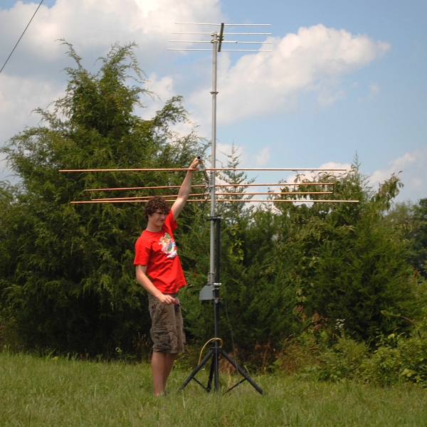
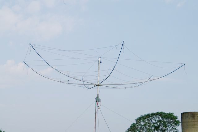
6m LFA Beam Dis-assembly
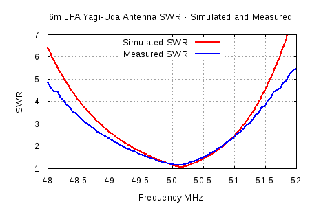
Comparison of 6m LFA Yagi-Uda Simulated and Measured SWR
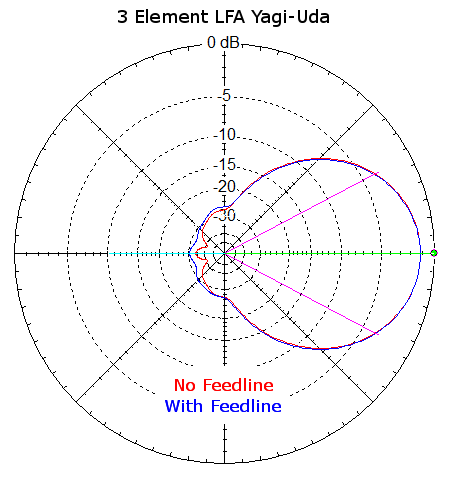
Azimuth Plots of LFA Yagi-Uda with and without feedline
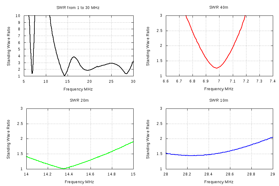
SWR Measurements of LNR Precision EF-10/20/40 End Fed Antenna
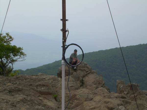
Rob as seen through the 2m Collinear J-Pole Coil Choke
Only a ham would considering this a poetic portrait of a person atop Hawksbill mountain.
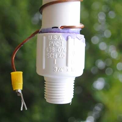
2m Collinear Coil End
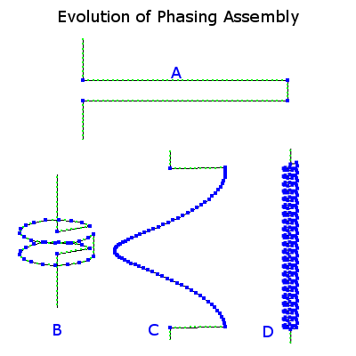
Various Phase Stubs for Collinear J-Pole
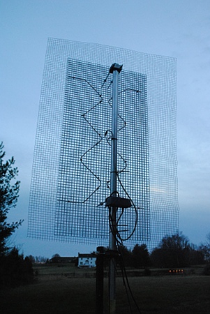
Hoverman UHF DTV Antenna
Another view of the Hoverman antenna. The Channel Master 7777 pre-amp is seen in this view.
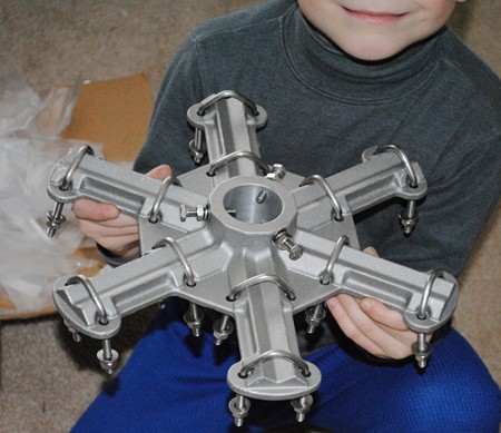
The Hex Beam Hub is ready for the next part of the Hex Beam project.

Hex Beam and K2 Contacting Hawaii
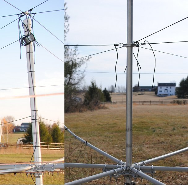
Traditional vs. Metal Hex Beam Mast
On the left is the usual non-conductive center post mast used for hex beam antennas. The material is often fiberglass or PVC pipe. On the right is a new all aluminum center post mast. An additional non-conductive post will be placed next to the mast for the hex beam feeders. See the article elsewhere on this site for details.
05_dxe_43_foot_antenna_ready
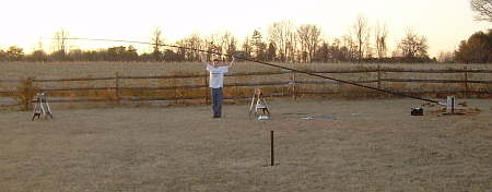
The aluminum antenna pieces are all together resulting in the 43 foot finished result. It was assembled while attached the the Tilt-Base mount and is shown here ready to raise. It is a very light, but very wiggly and cumbersome antenna.
09_looking_up_43_foot_antenna
Beautiful ain't it.
Up and ready for action.
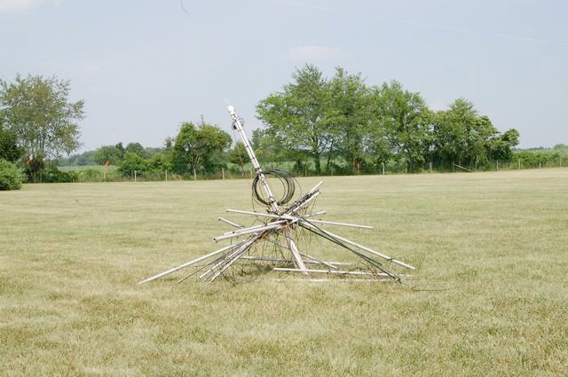
Jumbled mess of wires and poles
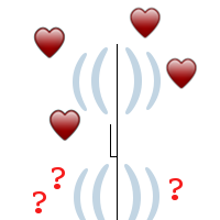
jpolelove
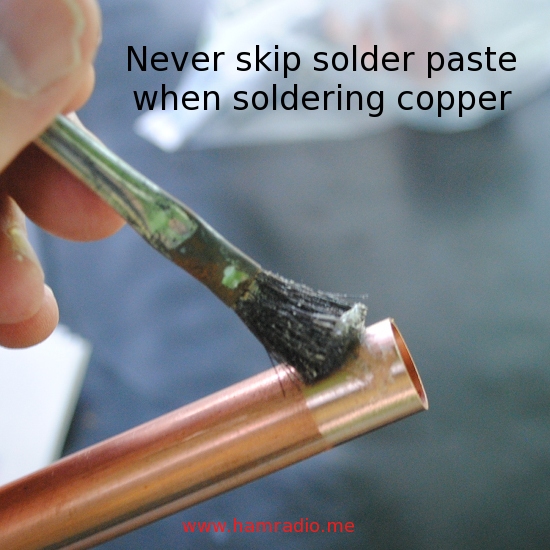
Flux
Link to XML Sitemap – http://www.hamradio.me/sitemap.xml