Deja vu
This is a follow-on to an earlier article discussing in particular the EFHW antenna. In this post we will focus more on comparing the EFHW against other HT antenna approaches.
HT antennas are often about what sucks least
Ever curious about HT antenna efficiency, we performed some EIRP testing of a Yaesu FT1D transceiver paired with several antennas including:
- A laboratory reference dipole tuned to 146 MHz,
- Stock FT1D antenna
- Diamond SRH77CA 1/4 wave whip,
- MFJ-1714 1/2 wave antenna
Later a “tiger tail” was added to the system to understand just what these do to actual radiation of energy.
There isn’t any question that antenna systems of sub-wavelength dimensions can’t beat the Chu-Wheeler limits, but with careful engineering reasonable results are available.
EIRP testing
Good old antenna chamber measurements are the norm in this industry, but sometimes the attaching cables are too intimate with the item under test. This begs for a test method to measure the energy emissions from a radio’s own transmitter. Being self contained, no extraneous rf currents spoil the resulting antenna pattern and resulting radiated power measurement. Figure 1 shows one example of an item under test.

It is literally one FT1D transceiver and an antenna… that’s it. In this example the 1/2 wave MFJ-1714 connects to the HT with the stock antenna shown for reference. The tests were performed in an antenna chamber in an EIRP configuration with the most important point being no other conductors are involved. The EIRP values shown below are literally just the radio and antenna. The FT1D has packet beacon capability perfect to generate the periodic test signal.
In case you were wondering, the definition of EIRP comes from IEEE-145-1993…
2.120 effective radiated power (ERP). In a given direction, the relative gain of a transmitting antenna with respect to the maximum directivity of a half-wave dipole multiplied by the net power accepted by the antenna from the connected transmitter. Contrast with: equivalent isotropically radiated power. Syn: equivalent radiated power.
2.136 equivalent isotropically radiated power (EIRP). In a given direction, the gain of a transmitting antenna multiplied by the net power accepted by the antenna from the connected transmitter. Syn: effective isotropically radiated power.
Reference Dipole
Despite the absolute accuracy claimed by the test facility, it is never a bad plan to profile a well known reference antenna in the same test session… just in case. A dipole is the king of antenna references with its very own unit, dBd, defined as a gain reference. Hence, the FT1D was connected to a laboratory grade reference dipole and set in place for our first EIRP test seen in figure 2 below.
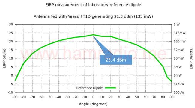
The test operator takes great pride in providing good absolute gain numbers. Let’s see how well he did with a review of the following points:
- Power measured from the FT1D during a packet beacon is 135 mW or about 21.3 dBm.
- Gain of the reference dipole was independently measured at 2.15 dBi.
- Expected EIRP = transmitted power + antenna gain = 21.3 dBm + 2.15 dBi… hence…
- Expected EIRP at peak gain ~ 23.5 dBm.
The average value of the top three points at -10, 0 and 10 degrees is 23.4 dBm. Very impressive and plenty close enough. Antenna gain at any angle in the data shown can be derived by subtracting 21.3 dB.
These EIRP tests also reveal the antenna pattern for 180 degrees of rotation. Hence we get two items from this test: radiated power plus an idea of antenna pattern. Good stuff.
Yaesu FT1D Stock Antenna
Our first test candidate is the antenna that comes with the Yaesu FT1D 2m/440 transceiver. Figure 3 shows the results along with the dipole reference for, you guessed it, reference.
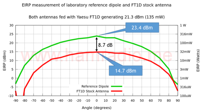
At almost 9 dB below the reference dipole, the stock antenna confirms the Chu-Wheeler limits apply. Smaller antennas mean lower efficiency and less signal. Still one wonders how this antenna compares with aftermarket alternatives meant to improve performance.
Diamond SRH77CA 1/4 wave whip
An obvious antenna to try is the ubiquitous 1/4 wave whip. Plenty of aftermarket options provide ample choices. The Diamond SRH77CA won the lottery to represent 1/4 wave whips for this test series. The markings on my test sample say SRH77A that I assume is the same at SRH77CA. There’s not a whole lot exciting about this… it’s just a piece of wire 1/4 wave in length for the 2m band wrapped in decent and flexible materials. Figure 4 includes this antenna along with the reference dipole and the FT1D stock aerial.
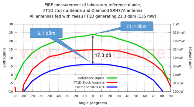
Whoa… the longer whip performs much worse than the FT1D stock antenna. -17 dBd!?! Put another way, the hundred or so milliwatts of effective radiated power has been whittled down to just a few – Hurl! A couple key observations include:
- The 1/4 wave whip seems to lust for the “other” 1/4 wave section in the quest to be a complete 1/2 wave radiating system.
- I correlate this measurement with my subjective observation that holding the body of the FT1D noticeably improves the reception of my local repeater. When the HT sits on my wood table, reception is much worse.
- With this new data, the FT1D stock antenna isn’t looking so pathetic.
It’s a good time to highlight the posted gain found in Diamond’s advertising copy.
- “*Gain (relative): +6dB” – Relative to what??!?!?!
- “*Rated against typical stock HT antennas.” – Oh really?
Oh how very cute… referencing your product’s antenna gain to any old thing you define. I guess it wouldn’t help them to use the FT1D’s stock antenna for reference as their 1/4 wave would ring in at about -9 dB.
It’s time to up the game to one of the end-fed half-wave antenna products.
MFJ-1714 1/2 wave end-fed dipole
A test series like this isn’t complete without trying one of the super long 1/2 wave antennas for HTs. Diamond makes one model that measures in at 5/8ths wave. However at just sixteen bucks, the MFJ-1714 got the nod. I ordered two: the BNC model and, for the FT1D, the SMA model. Let’s see the results.
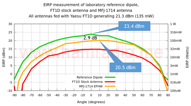
Well well the 1/2 wave antenna finally beats the stock antenna. Whether it crushes it in the HT antenna olympics depends on one’s perspective if that extra length is worth the trouble. Key points…
- The 1/2 wave whip seems to shun any need for any extra counterpoise in the quest to be a complete radiating system.
- I correlate this measurement with my subjective observation that holding the body of the FT1D provides no change to hearing the local repeater. When the HT with 1/2 wave sits on my wood table, reception is fine… much unlike the 1/4 wave.
- With this new data, the FT1D stock antenna still isn’t looking pathetic especially given its performance for size.
HT Tiger tails
Figures 6, 7 and 8 show the three test antennas with a 1/4 wave “tiger tail” connected to the outer conductor of the FT1D antenna connector. In each case the original measurement is shown as a dashed line with the new result as solid.
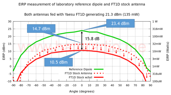
Hmmm that stock antenna is being so mysterious. It doesn’t like the addition of the tiger tail. Since holding an HT provides a bit of the same effect, one can only wonder how the EIRP holds up under varying conditions. Still it isn’t slaughtered by the addition of the tail. It really does seem to hold up relatively well under varying circumstances. So noted. Let’s see if the tail helps the 1/4 wave whip.
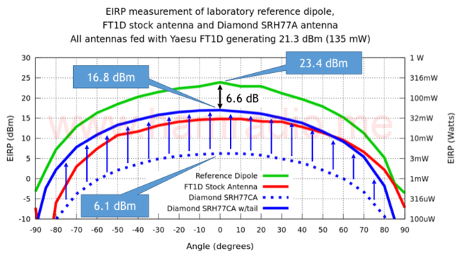
+10 dB… a stunning improvement don’t you think? With the tiger tail “completing” the “other half” of the antenna, we now have performance that just barely beats the stock antenna. Just barely? What? The mystery continues as the FT1D stock antenna holds its own against a 1/4 wave whip with dangling tiger tail. Time to check the half-wave antenna.
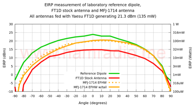
Hmmm… no improvement or degradation to speak of. For all practical purposes, the tiger tail is irrelevant to antenna operation. I guess this isn’t a surprise, but some might expect the addition of a 1/4 wave to the grounding side to change things more that what figure 8 suggests. This measurement leads credence to the EFHW aficionados’ creed the common-mode current of an end-fed antenna certainly exists, but is of smaller value and of little effect in the big picture. We won’t go into depth on this here since we are dealing with HTs, but will file this away as some evidence to include in future analysis of end-feds with lengthy feedlines.
Loss Factors
One nice thing about EIRP tests is its final arbitration of what works. Either the signal gets out well or it does not. These tests don’t specify exactly what causes poor power output. A partial list of loss factors include:
- Mismatch Loss due to impedance discontinuity;
- High VSWR power fold-back circuitry;
- Lossy antenna medium;
- Chu-Wheeler limit.
Mismatch Loss
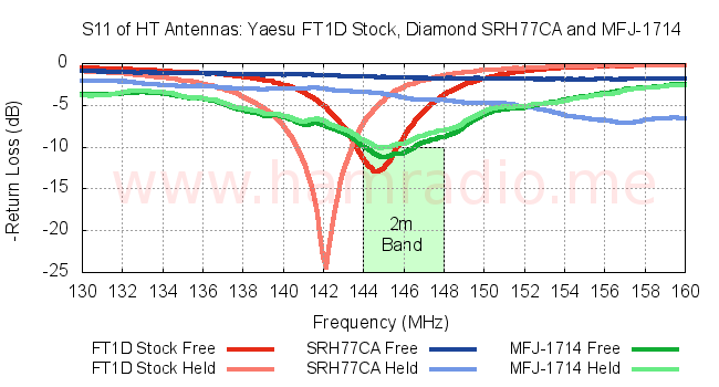
Figure 9 shows the Return Loss of the three HT antennas above using a reasonably well isolated (lots of ferrite) metal mock up of the FT1D. Each antenna was measured twice: once with nothing touching the mock up case and once with my hand holding the case. Figure 10 shows Mismatch Loss of the same.
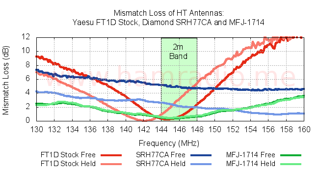
Observations…
- In general the world of HT antennas is treacherous thanks to wildly swinging environmental variables.
- The stock antenna for the Yaesu FT1D tunes below the 2m band when held, but settles in pretty well for part of the band when not and does so with very respectable return loss.
- The Diamond SRH77CA whip is pretty tragic alone and only a little better when held. The tiger tail would probably improve this measurement a lot. Mismatch loss is high (a couple dB or more) and the transceiver likely folds back combining for the poor showing on EIRP without the tiger tail.
- The MFJ-1714, after a light shortening of the telescope element, settles in around 8 dB Return Loss (under 1 dB Mismatch Loss) for the entire band. It’s remarkably immune to handling as well.
Another EIRP test performed on the FT1D with its stock antenna, compared standalone vs. my holding it. Holding it reduced the 146 MHz EIRP by 3-4 dB… inline with the behavior seen in figure 10.
HTs live a tough life electrically. The best performer of the above is the 1/2 wave whip with passable Return Loss across the entire band plus some end-fed half-wave immunity to variations in counterpoise.
Power Fold-back
The folk-back circuitry is a big factor for poorly matched antennas. The radio must protect itself from antenna-port evil. If I could place a power meter inline of the FT1D antenna port to see if that 1/4 wave performance was due to fold-back, I would. Such an invasive test is difficult to accomplish without changing the mechanical reality of the antenna system so EIRP tests will have to do.
Lossy antenna medium
As the definition of antenna gain is antenna directivity including antenna conductive losses, we must keep an eye out for poor conductors in our antennas. Fortunately most amateur antennas are made with materials plenty conductive enough to not be a problem. When antenna dimensions are small for the wavelength and feed impedances plummet, conductivity becomes a larger factor.
Chu-Wheeler-Harrington limit
Every college antenna text shares lamentations of the never ending quests for ever smaller antennas. A “TON” of cash is thrown at this problem by various entities. Sadly as antennas shrink they become ever more difficult to operate efficiently. Chu, Wheeler and later Harrington offer guidance on what happens as antennas shrink. Antenna currents soar. Bandwidth narrows. Feedpoint impedance plummets and becomes more reactive. As the FT1D stock antenna suggests, reasonable performance is possible so long as one manages expectations. Other electricall small examples are the various small transmission loops, such as mine, made with thick conductors operating with very narrow bandwidth.
Don’t knock stock
For me the most impressive result of these tests is how well the Yaesu stock antenna performed in varying circumstances. Yeah there’s no question it can’t complete with full length half waves, but it may well have the best performance per unit length. As far as I’m concerned it laughably beat the 1/4 wave whip. Sure the tiger tail evened the score, but come on… a 7 inch stock antenna verses a 19 inch whip with some awkward, dangling wire getting in the way. The tiger tail is a fine and practical idea to “fix” the 1/4 wave whip, but adds clumsy bulk for little improvement in performance over the stock antenna. At least that’s what we learn in the above FT1D case.
It appears the engineers at Yaesu have heavily optimized the antenna supplied with their FT1D very well to yield a “system” that performs the role of “HT transceiver” about as efficiently as possible and with some immunity to extraneous influences. I see this in other quality products as well. Motorola comes to mind with their RMM2050 MURS portable radios. These 152-154 MHz HTs have an even shorter whip than the FT1D. Despite this puny aerial, the RMM2050 is the best performing MURS radio I have seen in the volunteer events I work. I credit Motorola with two advantages: They probably produce every bit of of the two watt legal max power and efficiently couple this to an antenna/housing combination specifically designed just for 152-154 MHz. This just goes to show a manufacturer that cares can produce radio/antenna combinations that make the absolute most of the available constraints.
The moral of the story is pretty simple. Don’t jettison the antenna that came with your HT so quickly without some due diligence. If the antenna’s appearance shares decorative traits with the HT, there is a good chance the designers spent time ensuring the two work well together electrically. Where this is true, you are probably not going to find an aftermarket HT mountable antenna solution providing better performance for the size and sometimes even for larger size.
Conclusions
My original goal for this test series was to confirm if the end-fed 1/2 wave antenna needs a more spectacular counterpoise than supplied by the body of the HT. “Not really” appears to be the answer. More tests are coming to clarify and confirm this finding.
It was nice, but yet surprising, to see the stock antenna hold its own as well as it did. This does match my subjective and potentially biased observations, but it’s nice to have confirming data. You always wonder if amateur gear gets the same engineering attention as commercial offerings. At least with the Yaesu FT1D, the answer appears to be yes. In general size matters for antennas, but we also see good engineering yields compact antenna efficiency.
The 1/4 wave whip brings little value IMO. Yeah you can “fix it” with a tiger tail, but that’s fixing your original fix. Kind of silly when you think it through.
My personal takeaway from all this research concerning HT portable operation is…
- I will use the stock antenna on my FT1D for almost all purposes and
- Use a rollup 2m J-pole from N9TAX or Fong for the truly tough radio circuits.
There isn’t much that’s going to beat an efficient vertical dipole hanging in a tree. A case can be made to slide one of the MFJ 1/2 waves into your backpack to give your HT a slightly better punch for challenging situations. It’s cheap insurance at $16. The Diamond 5/8th wave HT antenna is another choice for the “go to” antenna/signal boost.
Great article.. I'll be the first to comment. As I was searching for different "tiger tail" articles, I found this. As I have used a tiger tail with a stock rubber ducky on 2 meters with a cheap TYT dual bander 144 and 220 mHz, I found that with that antenna, it made just enough of a difference with a base station about 10 to 12 miles away. Keep in mind, however, the base station had a very good antenna mounted high and away from any buildings and/or trees. Without the tiger tail attached, the base station could not hear me. With the tiger tail attached, a qso could easily be made. It may have been such a small difference, but it was just enough to get through. Seeing your results confirms for me that a roll-up j-pole for dual band or some other such antenna (external) would be the best bet if you have a place to hang it. Or the half-wave telescopic if you just can't make it. But for every-day use, I'll just use the stock antenna and keep it simple! Another note: I wonder how the MFJ half-wave would behave on 440mHz if only extended to the half wave on 440?
It had the same experience with tiger tail. I was able to register 2S units with tiger as opposed to without. That's a significant improvement over just a rubber ducky.
This almost perfectly matches my son's science project from last year in concept, with similar results, though he used a more rudimentary testing method. Do you have any pictures or methodology description of how the antennas were tested?
https://www.google.com/amp/s/phys.org/news/2017-0…
Chu-Wheeler limits apply only to passive antennas. The phys.org article refers to active antennas and has been lampooned often in antenna circles for attempting to blur the lines to suggest some new achievement.
Thank you for the insightful article. It was quite refreshing to find some actual controlled tests and results of various HT antennas after reading many anecdotal reports.
I am curious if you have any additional thoughts about why there is a large (6.6 dBm, per Figure 7) difference between the laboratory reference dipole and the 1/4 wave antenna with a "tiger tail"? Isn't a 1/4 wave whip with a 1/4 wave "tiger tail" essentially a dipole antenna? I expect there would be some differences in EIRP due to proximity of the HT to the antenna and possibly differences in element length/tuning, but 6 dB seems pretty significant for an antenna that is approximately the same design.