In Part 1 of of “EME on a Budget” we introduced EME and discussed operational basics and propagation.
We now move on to the essential requirements for an EME station.
EME Station Requirements
This section begins with an outline of station requirements because for many readers the bottom line is going to be – well, the “bottom line.” Later on I’ll discuss the details of how my station is assembled and outline the basic set-up requirements, but if the projected costs discussed in the following paragraphs are too much of a “turn-off” for any reader to consider then there is no point in him or her going beyond this part.
Based on a lot of study and my own practical experience a reasonable “minimum station” for achieving successful 144 MHz EME digital communications with larger stations would look something like the following. It can be done with less, but for repeatable success this list is probably a reasonable yardstick to use.
- A VHF multimode transceiver capable of 144 MHz SSB operation, with output sufficient to drive an outboard amplifier. IF A HIGH STABILITY REFERENCE OSCILLATOR OPTION IS AVAILABLE IT WOULD BE PRUDENT TO PAY THE EXTRA MONEY FOR THIS CAPABILITY. In Digital EME as in so many other things in life, “timing is everything.”
- A combination power amplifier & low-noise preamplifier (aka a “brick”) having a power output of 100 watts or more and a preamplifier noise figure of less than 1 dB (and the lower, the better). THE UNIT SHOULD BE INSTALLED AT THE ANTENNA. (NOTE: Don’t panic, this is much easier than it sounds.)
- A DC power supply to be situated outside to power the amp/preamp.
- A Yagi antenna with a forward gain of at least 12 dBd. THE ANTENNA ONLY NEEDS TO BE MOUNTED 7 TO 10 FEET ABOVE THE GROUND.
- A small rotor for azimuth adjustment of the antenna (a TV rotor will suffice) is recommended although manual azimuth adjustment can be used if not too much of an annoyance. Some form of elevation adjustment is recommended, even if only manual, but EME contacts can be made during the first hour after Moonrise or the last hour prior to Moonset without it.
- The shortest possible (50 feet or less is a good rule of thumb) low-loss coax between the transceiver and the amp/preamp. “Low loss” means, AT A MINIMUM, Belden 9913. LMR-400, EcoFlex 10 Plus and AirCom Plus are better still.
- A radio/PC interface controller such as a Rigblaster by West Mountain Radio.
- A desktop or laptop PC installed at the operating position. Windows XP or later are recommended operating systems, and WSJT Version 9 (which is FREE from the WSJT website) should be installed.
- An accurate time-stabilization program (such as Dimension 4, which is also free) should be installed on the PC.
Here is how the basic costs break down:
- TRANSCEIVER: Whatever you choose to spend.
- AMP/PREAMP: Up to $450 new depending on brand; less if purchased used.
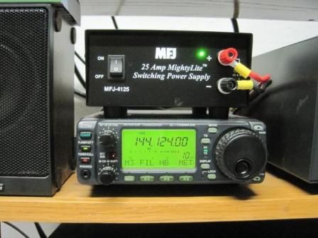
- POWER SUPPLY: Up to $200 for a new linear-type. I paid $105 shipped for a new MFJ switcher (compact, reliable, and there are *NO* noise problems with it!).
- ANTENNA: $225-$250 including shipping and/or local sales tax (if bought from HRO).
- TV ROTOR: ~$100.
- LOW-LOSS COAX: ~$60-$120 depending on type and length.
- INTERFACE UNIT: $160 for a Rigblaster Plus II.
- PC/LAPTOP: Whatever you choose to spend
- WSJT and Dimension 4 software: FREE
The bottom line of the above list is that, discounting the transceiver, power supply in the shack and the PC, the remainder of the equipment for 144 MHz digital EME can be purchased for around $1,300 (BOLD-FACED maximum prices above). By judicious shopping and using eBay, eHam classifieds, etc., this can be cut considerably and if you already have some of the equipment the cost will be even less.
The K4MSG 144 MHz Digital EME Station
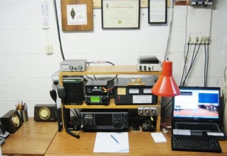
1. Icom IC-706MkIIG transceiver with a Dell laptop running Windows XP Professional, loaded with WSJT Version 9 and Dimension 4 time synchronization programs. A Rigblaster Plus interfaces the radio with the laptop. The laptop also utilizes a wireless connection to a home router for Internet connectivity for the Dimension 4 software and for monitoring the N0UK EME Chat Page; this last is useful for setting up QSO attempts in real time if prior scheduling hasn’t been done.
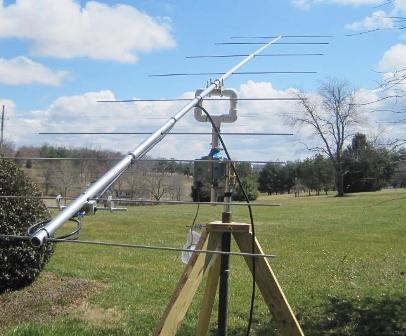
2. A M2 2M9SSB 9-element Yagi (14.5’ boom) mounted on a home-made wood tripod with a TV rotor for azimuth control and a homebrew manual elevation adjustment.
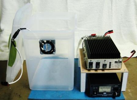
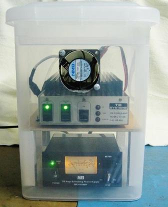
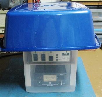
3. A TE Systems 1412G 200-watt, 144 MHz amplifier/preamp (0.5 dB preamp noise figure) located at the antenna. Approximately 13 feet of AirCom Plus which was in the junk box connects the amplifier to the antenna, but EcoFlex 10 Plus has almost the same characteristics. An MFJ-4230MV 13.6 VDC metered, variable 30-amp power supply is co-located with the amplifier. The metered supply provides a visual check on whether the amplifier is keying during transmit cycles (by walking outside and noting the current draw on the supply meter) and the variable output allows adjustment of the DC output voltage to compensate for AC voltage drop through the extension cord from the house to the antenna. Note that this power supply is no longer manufactured but I found a source of brand-new in-the-box units on eBay for $105 shipped.
4. Initially, 50 feet of Belden 8214 low-loss RG-8/U coax was installed between the transceiver and amplifier. This was used for the first couple of weeks because the cable was in the junk box but the loss is a little worse than Belden 9913 so it was subsequently replaced with EcoFlex 10 Plus. If you’re buying new, just buy the EcoFlex ($1.19/foot from Universal Radio). A similar length of 4-wire rotator cable connects the rotor control box in the shack to the rotor.
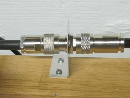
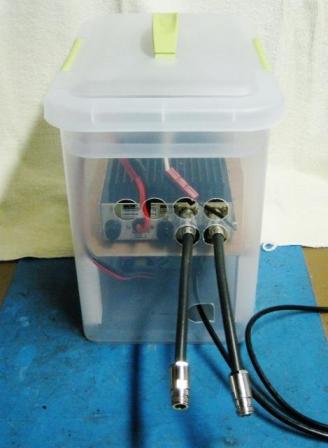
A few words on connectivity: The IC-706MkIIG uses a UHF output connector and the TE Systems amplifier uses UHF input and output connectors, while the antenna uses a Type N connector. As you will note from the photographs I use a short UHF to N coax “stub” on the transceiver output and also on the amplifier input and output to make connecting and disconnecting the equipment easier (in the transceiver case for switchover to my terrestrial 144 antenna, and in the amplifier case to speed up the connect/disconnect time of the portable “amplifier box”). Because of this the transmission lines from the shack to the amplifier and from amplifier to antenna use Type N connectors. These cost approximately $10 each for Type N connectors to fit the EcoFlex 10 Plus cable. Type N connectors are also waterproof, a big plus when it’s raining while I’m operating EME with the amplifier box outside.
Thanks to already having a suitable amplifier/preamp, a Rigblaster and low-loss coax, I spent ~$500 to get on 144 MHz digital EME. Almost half of that amount was in the antenna and the balance was in the second power supply (for powering the amplifier outside), the rotor, and a few miscellaneous items.
EME Equipment Photos
The photos that follow illustrate how my initial 144 MHz EME station is configured. Captions on each photo explain the set-up and suggest what is necessary to duplicate the configurations shown.
End of Part 2
There are countless possibilities for configuring a single-Yagi EME set-up and the descriptions and photos above merely indicate one approach. While I would recommend a minimum of 12 dBd antenna gain, 150 watts at the antenna and a preamplifier noise figure less than 1 dB, if you have better capabilities available (or more cash to spend on equipment) by all means do so. The better the initial set-up the better will be your results.
In Part III we’ll take a look at actual EME operation using JT65b.


Nice system, thank you for sharing your experiences. I have an rf amp/preamp & using your experience, will mount them at the antenna enclosed in plastic boxes such as yours.
I'll have 2x or 4x 13 element yagis and up to 1kw to put into them. Will let you know how it works.
Best 73's
George KM6UM
Does the moon's position in the sky change over time or does it traverse the sky in the same path every day ?