Field day 40 on the cheap
Just in time for Field Day 2013…
Here is concept antenna you may find worth trying. This answers the call for when you do not have any mast or trees to work with, but still desire 40m contacts.
As with previous efforts [1][2], it makes use of ladder line in a folded dipole configuration with one additional reflector wire. The reflector wire improves the signal by about 3 dB over a single wire antenna.
No mast in this context means no structure taller than a person. My criteria means the whole antenna is lower than 6 feet above ground level.
The Folded 40m Concept
Below is a schematic of the basic idea behind this antenna.
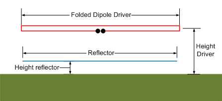
Highlights:
- The red lines reveal the parallel ladder line or equivalent wires set up as the driven element.
- The blue line shows the slightly shorter parasitic wire hovering above the ground to help mitigate some, but not all, ground losses.
Ladder Line Element facilitates 50 ohm feedpoint
As with any multi-element antenna, parasitic elements load the driver, therefore, lowering feedpoint impedance due to mutual coupling. Such is the case when you add the reflector wire underneath the element in the design above. The classic way to mitigate this is make the driver element’s “natural” impedance much higher than 50 ohms with the goal of “loading” it down to 50 ohms in the presence of the reflector and ground. This is much like how the Loop Fed Array Yagi Antennas work.
My simulations suggest you can make the “ladder” line with your favorite wire and simply space it an inch or two apart. The closer the spacing the more supports you will need to ensure the parallel wires do not touch or cross.
True ladder line is more convenient for the driver and readily available from local sources.
Reflector Wire
As previous efforts suggest, adding one or more reflector wires beneath the driver in any NVIS configuration usually helps the signal by a noticeable amount [1][2][3]. We make good use of that here, but with just one, more portable, wire. Adding the reflector wire helps by…
- Reducing energy lost in heating the ground,
- Increasing the gain of the low dipole by about 3 dB,
- By adjusting its length and height with respect to the driver, we establish a mechanism to “adjust” the antenna for best gain or best SWR.
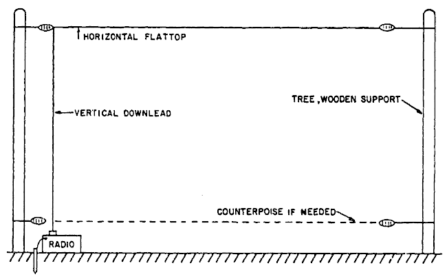
There is nothing new or novel about reflector wires underneath horizontal antenna elements destined for NVIS service. An example from 1981 DOD antenna handbook…
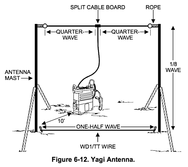
…and this relatively recent publication from the USMC…
…to add to the experiments performed by amateurs [1][2][3]. Our use of NEC merely helps us use this extra wire to refine the whole antenna system rather than simply throwing a wire underneath the driver and hoping for the best.
Folded Dipole/Reflector Element Lengths
The table below is the result of several iterations of NEC using the 4nec2 evolving routine. Originally I focused on a design for best SWR and then for best gain. Other antenna configurations, like the full wave loop for example, benefit from this. In the simple dipole I found less than a dB advantage with optimizing for gain. So the three sets of dimensions below are all focused on best SWR.
| Frequency | Folded-Driver | Reflector | ||
|---|---|---|---|---|
| Length | Height | Length | Height | |
| 7050 kHz | 68.1 Ft. | 5.5 Ft. | 67.6 Ft. | 0.7 Ft. |
| 7150 kHz | 67.1 Ft. | 5.5 Ft. | 66.7 Ft. | 0.7 Ft. |
| 7250 kHz | 66.2 Ft. | 5.5 Ft. | 65.7 Ft. | 0.7 Ft. |
…and in metric…
| Frequency | Folded-Driver | Reflector | ||
|---|---|---|---|---|
| Length | Height | Length | Height | |
| 7050 kHz | 20.76 m | 1.68 m | 20.61 m | 21 cm |
| 7150 kHz | 20.45 m | 1.68 m | 20.32 m | 21 cm |
| 7250 kHz | 20.17 m | 1.68 m | 20.04 m | 21 cm |
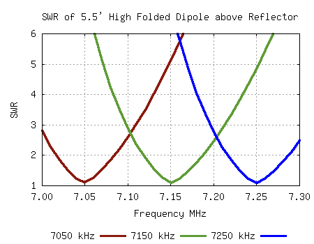
The above measurements assume bare 14 AWG wire. Different wire size will change the measurements. Insulated wire or “window” ladder line will require shortening the lengths. Where the best frequency is depends on your materials, but wherever it is it will likely have these SWR and Gain profiles…

Shorter Reflector?
I found several combinations of wire lengths that produce good SWR and acceptable Gain around 3 dBi. These include traditional Yagi-Uda style wire dimensions where the reflector is a bit longer than the driver [3]. However, I frequently find when the reflector is near the ground, having it a bit shorter than the driven element produces a bit more gain. Such is the case in this particular design.
Narrow Band
Unfortunately this antenna will not cover the entire band without external tuning. One good solution is to feed this with ladder line from a good antenna matcher. Short of that, you can make this antenna too “short” and then lengthen it with short ladder line stubs as shown here…
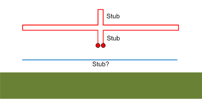
Ladder line to dual banana posts and jacks make for a quick and easy way to add these stubs.
To maintain perfect balance of currents, the design needs both stubs in the driver. Theoretically a stub in the reflector keeps the antenna at its very best, but to be honest, there is a point where too much is, well, too much. The simulations show the antenna still functions quite well with the reflector as is. Really you can get away without the second stub on the driver… just remember to double the length of the one stub. Your choice.
The, of course, you can simply press the “tune” button on your rig and see what happens.
Electric Fence Stakes
The horse and cattle industry provides an ample supply of remarkably sturdy white solid fiberglass poles. Your local farm supply store likely carries at least the four foot long variety. They come in lengths up to eight feet and more. I specified a 5.5 foot tall dipole in this article with the intention of using 6 foot fiberglass poles pressed into the ground six inches.
The electric fence posts have companion metal clips that you can adjust to any height with a simple squeeze and slide. This is absolutely wonderful for antenna fiddling.
Here is one source…
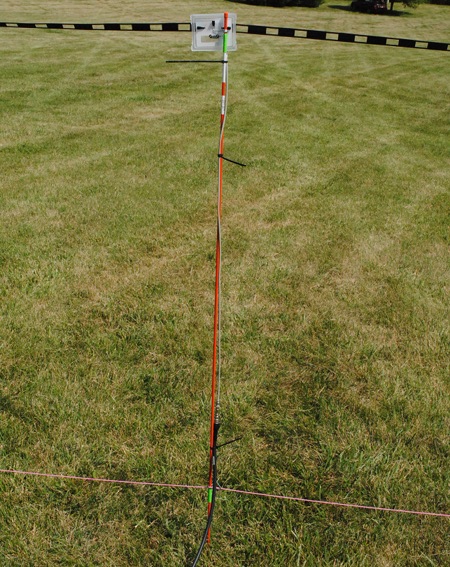
For a high visibility option search for “hillman orange reflective rod” in your favorite search engine. Lowes has them. They are not designed to hold wire like the fiberglass above, but some thought can make these work. I used them for this Field Day prototype…
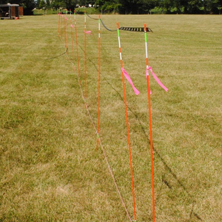
Unfortunately the rods are more narrow than the web site suggests so the clips I purchased from a local farm center were too large to grip. I used green duct tape to hold the clips in place. I will be searching for a better solution.
Being non-conductive you can use as many as you like. The more posts you use, the less chance of your dipole turning into a Field Day nighttime human trap.
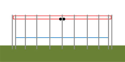
In the diagram above you have a squeeze-and-slide wire clip everywhere a wire crosses a post. Simple, cheap and quick to set up.
Good, but not great, NVIS performance
It should come as no surprise this is strictly an NVIS type antenna.
I should also point out this antenna, being so close to the ground, is not an ideal configuration for maximum NVIS signal. The following graph compares:
- the 5.5 foot high wire over ground (Red),
- the same wire over the additional reflector wire (Green),
- and a 40m inverted V dipole with the apex about 35 feet (Blue).
All three plots show the elevation gain profile broadside to the axis of the wires.

If you have the facilities to hoist a 40m dipole in an inverted V or higher configuration by all means do so. It will be better than the 5.5 foot high dipole. Note, however, the additional reflecting wire significantly improves the performance of the reflectorless dipole making it almost as good as the Inverted V.
If you are looking for a very simple, but reasonably effective, 40m antenna for your portable operations, this article is a recipe for one that should yield about 3 dBi gain straight up.
Experiment
If you build this antenna using the above dimensions, make it a bit long and trim the driver to your target resonance. If all you care about is CW, you can make this cover that with ease by making it longer with a corresponding increase in the reflector. Eventually I will test a real antenna and provide a drawing with various recipes for various materials.
Natural Balancing Feedpoint needs no Balun
The folded dipole in combination with the reflector wire provides you with a 50 ohm feed and no need for a balun (although you can use one if you wish) as full wave loops are self balancing to a great degree [5]. The reasons why may be found in the LFA article.
The Reflector is your SWR Optimizer
After you have the target resonant frequency you should be able to optimize the SWR by adjusting the height of the reflector. Leave the folded driven element as high as possible on the posts and use the reflector wire height to “tune” the antenna. Anywhere from on the ground to 2 feet are possible. I found 1/2 to 1 foot to be good spots in the simulations.
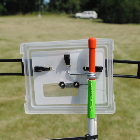
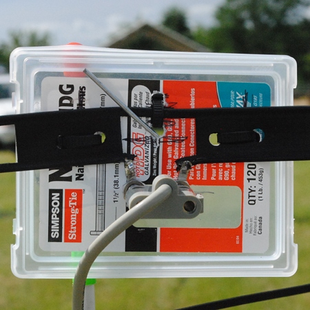
My Prototype of the Mastless 40m Dipole
My hastily built prototype offers promise for Field Day 2013. I made the driver with some 14 AWG stranded ladder line and the reflector with some 14 AWG pink “hookup wire”… more visible for Field Day visitors you know 😉 I built it long and came in with an okay SWR at 6.9 MHz. After trimming from both ends (and re-shorting the ends by twisting them together) I reached about 7.18 MHz. I was aiming for 7.15, but oh well. SWR was about 1.8. I them trimmed the reflector quite a bit and got down to 1.5 at 7.2 MHz. Good enough. I hooked up the QRP rig, touched the tune button, and made two solid contacts to Ocean City and West Virginia clearly via NVIS. Solid signals both ways. So it does function. I packed it up for the Field Day GOTA station. Here are some photos…

We did not have many visitors to our 20m and 40m only GOTA this year, but the few who did visit had no trouble closing the deal with 40m contacts using the above antenna. By the way, the 20m antenna was the experimental Asymmetrical Hatted Vertical Dipole prototype.
Your version?
If any of you decide to tackle this, please keep notes and let me know your measurements and experiences. I’ll post my actual dimensions for the materials I used after Field Day.
References
- Dusina, Ed “A Super-Gain Antenna for 40 Meters.” Amateur Radio 73 Magazine. October 1969: Pages 8-11. Print.
- Barry, Jerry. “A Super-Gain Antenna Project for 40 Meters.” http://www.hamuniverse.com/supernvis.html
- Glover, James R. “The Cloud Warmer NVIS Beam.” http://www.hamuniverse.com/nvisbeam.html
- Kershner, Stephen. “High-Frequency Antennas.” Antenna Engineering Handbook. Ed. Henry Jasik. New York: McGraw-Hill, 1961. 1st ed., pp. 21-4. Print.
- Buxton, Carey G., Warren L. Stutzman, Randall R. Nealy and Aaron M. Orndorff (2001). The folded dipole: A self-balancing antenna.
Revisions
- 2020-06-06 – Added graphic in support of Kershner and Jasik reference #4.


Wonderful articles, just found you/ I used a very low NVIS END FED with a CHAMELEON HYBRIDE 2.0 balun three feet off the ground
with three reflector wires and it works great.
I am putting up a 9 foot quad loop and am going to elevate the reflector wires6 inches off the ground and try that. Normally the three uninsulated reflector wires are on the ground.
GREAT STUFF thanks again
George Riedel N1EZZ