Antenna tilt
Ever wonder how sensitive our mobile antennas are to antenna tilt? Data from a previous test of antennas on my small SUV show a pattern tilt correlating to an approximate 5 degree antenna tilt towards the centerline.

The tilt of the NR770HBNMO antenna leans toward the car’s left side (to the right in the figure’s front view). The green trace from the tilted antenna seems to have a corresponding beam tilt as well. Hmmm.
Is antenna tilt this sensitive?
Ever the inquisitor, I just had to check things out. So back testing the Forester and its Diamond Antenna NR770HBNMO atop the K515S luggage rack mount.
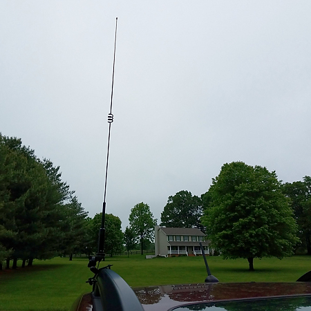
The K515S mount can adjust the whip front to back and side to side. Figure 2 shows the slight inward side-to-side angle used in the previous tests. The whip is also angled slightly back… a result from thwacking one too many limbs in its short one year of use. The three tests were…
- Whip tilted back about 4 degrees with side to side angle inward 5 degrees.
- Whip tilted back about 4 degrees and side to side angle at 0 degrees.
- Whip tilted back about 4 degrees with side to side angle outward 5 degrees.
In other words, the front to back tilt did not change at all and side to side was set to three different angles.
VHF front to back antenna pattern

As the front to back tilt doesn’t change from test to test, it’s reassuring to see the patterns remain the same. One can argue the slightly higher peak towards the front corresponds to the 4 degree back tilt of the antenna. It may also be due to the off center conductive surfaces of the Forester. Or both.
UHF front to back antenna pattern

The front to back antenna pattern for 446 MHz on the NR770 whip hugs the horizon a bit more. If there is sensitivity to whip angle, it will be more critical here than at VHF since the antenna is of collinear design. Thankfully for the constant front to back angle, the three patterns overlay almost perfectly. One can argue the slight backwards tilt of the antenna correlates to the slight rise in the front and fall in the back.
The astute reader might wear an expression of concern for the first nulls in elevation: about 20 degrees up in front of the vehicle and a bit less elevation to the rear. The NR770 certainly concentrates energy towards the horizon, but with risky dips in gain at slight elevations.
Interesting stuff. Let’s press on to the side to side tests.
VHF side to side antenna pattern

For 146 MHz there is practically no discernible change in antenna pattern for -5, 0 and +5 degrees from vertical. The NR770 is an end fed single dipole at VHF, hence antenna tilt at VHF is quite forgiving. No worries.
UHF side to side antenna pattern

Side to side antenna angles at UHF reveal positive correlation of antenna pattern tilt to antenna tilt. The NR770 is a double collinear at UHF, therefore, like figure 4, its horizontal pattern is flatter and generated by two collinear dipoles with decent vertical separation. Antenna tilt literally positions the two in-phase dipoles at significantly different horizontal locations, hence it’s no surprise to see the entire pattern being quite sensitive to very modest angles from zenith.
The energy towards the horizon remains relatively constant vs. antenna tilt. As in figure 4, those low angle nulls cause concern and may be a case where good peak gain is not necessarily the best overall pattern.
The quarter-wave aficionados may have a point
There is a vocal chorus on The Zed and other ham watering holes suggesting a 1/4 wave whip performs better for general repeater use than higher gain antennas like the NR770.
Let’s call up the VHF measurement from a previous test (same test session that made figure 1 above).

The half-wave antenna certainly wins on gain, however both win by not having deep nulls just above the horizon as in figures 4 and 6 above. If the antenna, let along the entire vehicle, tilts for whatever reason, the above antennas won’t present a deep null towards your repeater as easily as the NR770 at UHF.
Many of the 1/4 wave proponents focus their reasoning on high elevation, hence high angle, repeater antennas. Their usual logic flows thus…
The repeater antennas are up high on mountain tops as to require high angle user antennas to hit em.
Canyons like Sedona, Arizona aside, most circumstances are practically flat as covered in Repeaters, antennas and trigonometry. This figure highlights the luxurious case of a mile high HAAT repeater.
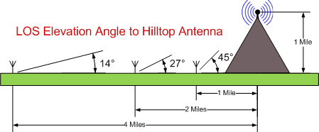
Yeah those in the shadow of such a hill will have problems using a collinear antenna. On the other hand, most users in the repeater coverage area, and a large area it is with a mile high HAAT, benefit from low angle radiation.
However even if the repeater antenna pattern lights up the horizon with rf energy, we do have to think about difficult to penetrate obstructions local to the mobile operator.
Diffraction
We all drive past obstacles and trees while chatting away on our local repeaters. We cover diffraction a bit here. Diffraction over these objects helps keep our radio circuit viable as conditions constantly change. The deep, low angle nulls of figure 4 and deeper nulls of figure 6 suggest diffraction possibilities may be seriously reduced in many situations.
Conclusion
Antenna tilt matters mostly for higher gain collinear antenna designs.
Personal observations of the Diamond NR770 antenna suggest solid performance at VHF. I observe incredible results for UHF when lots of open space is between the radio antennas. For typical situations where obstacles abound, such as going mobile along country roads while accessing the mountain top UHF repeater, I observe frequent and deep reductions in signal strength. I do wonder if a 1/4 wave antenna would be more appropriate.


