Why does a dipole fed at its end work?
There is an interesting Zed-Thread[1] concerning the apparent inequity of currents either side of a dipole’s feed position other than midpoint. Most everyone agrees with the following points:
- A dipole antenna is a dipole because of antenna function[2] rather than antenna feed method;
- The voltage to current ratio (aka impedance) vary along the length of the dipole;
- Generally speaking, the impedance of the feedpoint increases with distance from the antenna center;
- The center of the dipole antenna has higher currents and lower voltages;
- The ends of the dipole antenna have higher voltages and lower currents;
- Kirchhoff’s circuit laws[3] apply for distances much much shorter than an electrical wavelength.
I will add and some might agree:
- The center of a dipole antenna never has zero voltage;
- The ends of a dipole antenna never have zero current;
- No matter the means used to couple a transmission line to the dipole, it can be thought of as a power source in series with the antenna conductor.
The QRZ thread is mostly concerned with the issues surrounding the end-fed half-wave antenna and the apparent paradox of the open end currents. Specifically, is a counterpoise a necessary component for dipole operation?
End-fed dipole feed techniques
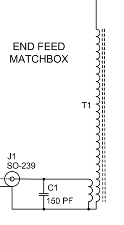
To simplify the discussion, this article will not consider the case where the the shield of the feed line has a galvanic connection to the antenna side such as this LNR Precision product reviewed earlier[4] with schematic shown thus…
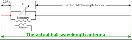
Instead the focus will be on the various methods leaving the antenna floating with respect to the feed line with galvanic isolation between the two. For end-fed dipoles, there is usually some sort of impedance step-up link coupling with a resonant tank circuit on the antenna side. A prime example comes from the seminal work by AA5TB.[5] The following schematic excerpt, with my additions in green, showcases the isolated style of EFHW antenna…
“The Question”
Understanding the end of a dipole is a high voltage, low current, high impedance point, everyone agrees the current from the right side of the transformer is of some small value with respect to the current at the antenna midpoint. The big question is what will the current be on the left side in red? After all, nothing connects to this point to wick current away so how can there by any current, let alone the logical compliment to the right current?
Another way to put this question…
Does end feeding a halfwave dipole require any additional counterpoise?
Observation from 1927 Patent AT110357
The EFHW antennas featuring link coupling have a direct lineage back to Josef Fuchs’ 1927 patent for the transmission arrangement shown in figure 3…
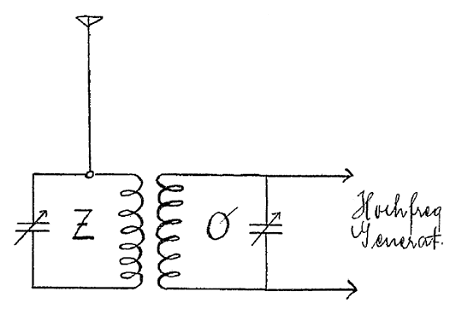
Fuch’s writes about a key observation (as output from Google’s German to English translator)…
The antenna is purely by voltage started the arrangement thus described has no counterweight or grounding of the antenna system.
“Purely by voltage started” clearly implies feeding the antenna element at a current node. I’m pretty sure counterweight in this context is counterpoise to most of us. So Joe says no. Interesting stuff. Let’s continue.
Revealing the entire half-wave antenna
The first observation I made about the above AA5TB diagram along with the others on his web site is the notion the end of the antenna is to one side of the transformer. I argue the transformer is actually “within” the half-wave antenna. This makes the transformer secondary winding a power source in series with and within the antenna. The green dimension line in figure 2 highlights this proposition. The same can be said of Fuch’s design.
The impedance seen by this series secondary winding depends only on position along the dipole element. This agrees with Stutzman and Thiele concerning half-wave dipoles with a “displaced feed.”
[. . .] there are several ways to change the input impedance of an antenna without using a matching network. [. . .] the input resistance of a dipole can be changed by displacing the feed point off center. [. . .] As the feed point approaches the end of the wire [. . .] the input resistance increases toward infinity. In practice, the input resistance becomes very large as the feed point moves out. The pattern is essentially unchanged as the feed point shifts.[11]
This still leaves the question of the current on AA5TB’s red wire.
Current has to go somewhere…right?
Right… but where? To answer this question I set up some simulations of a 10m half-wave dipole in a finite-difference time-domain (FDTD) electromagnetic simulation software.
Simulation model
For this simulation the model is idealistic and not reflective of real-world antennas with feedlines, etc. Madness you say? To some perhaps, but the purpose is to see if the dipole itself supplies everything one requires to resonate and satisfy Kirchhoff’s current law into the apparent dead end side of the EFHW power source. This addresses the quest of many participants in the above Zed Thread as they seek to understand where this current can flow.
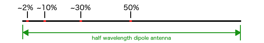
The choice of frequency is completely arbitrary as the model is in freespace of infinite extent. Hence the choice is a thin-wire dipole antenna with one source in series along its length… and that’s all. The position of the source various from midpoint (50%) to ever closer to the left end yielding four simulation runs shown in figure 4…

One cool thing with FDTD methods is the ability to watch electromagnetic waves evolve over time rather than view the stabilized final result as with NEC methods. In time I may put such “movies” online. For now snapshots will have to do.
Figures 7 through 14 show simulations of magnetic and electric fields of an infinitely thin, perfectly conductive, horizontal wire not visible in the graphics. To help visualize the wire, figure 5 shows the relative position of the simulated dipole along with the inline feedpoint position for each test.
Gain patterns for the curious
In case anyone might be wondering, the gain patterns for all scenarios, differing only in feed point placement, are essentially identical…
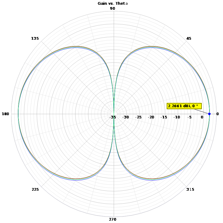
Figure 6 demonstrates the antenna pattern of a dipole antenna is not dependent on feed position. If one designs a real feed system to not radiate, the above classic dipole pattern should be the result. A non-radiating feed system is, of course, a challenge for center-fed, offset fed and end-fed dipoles alike. Those with NEC can easily confirm the above.
H-Fields of simulation dipole
The following four figures show the magnetic fields surrounding the simulated dipole antenna in each of the circumstances of figure 4. Colors show relative intensity. The magnetic fields nicely correlate with the electric current magnitude along the wire. Click for larger views.


In keeping with the definition of a dipole antenna,[2] it should come as no surprise the half-wave antenna pretty much works just fine no matter where we feed it. As currents dominate an antenna’s performance (usually), all four antennas will perform well.
E-Fields of simulated dipole
Moving on, the following four figures show the corresponding electric fields of the four dipole antenna models of figure 4. Colors show relative intensity. The electric fields nicely correlate with the electric potential (voltage) magnitude along the wire. Click for larger views.


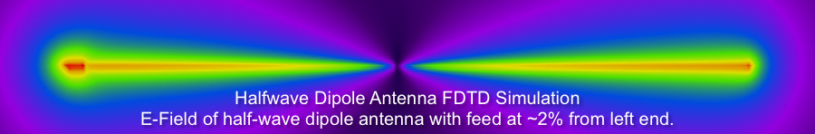
For the most part, the electric fields are high at the ends and low in the middle. No surprise right? However, some differences are seen as we move the series power source leftward. Looking at the 2% case the electric field, and by inference the voltage on the antenna wire, is much higher to the left of the power source than the right. This is a very good clue.
If we can believe the current to the left and right of the source is, more or less, the same value, what happens with the very different wire lengths on each side?
- The current to the right is free to flow along the length of antenna wire. Changes in voltage and current follow the typical variations one sees along an antenna.
- The current to the left faces a far different challenge. With nowhere else to go and with current flow coming whether we want it or not, the flow facilitates charging. Charging leads to voltage increase. Voltage increase leads to strong electric fields. Strong electric fields lead to…
Energy Storage via Maxwell’s Displacement Current
Any energy that doesn’t leave the antenna (and stay that way) must necessarily come back to the elements. Antenna currents and voltages induce magnetic and electric fields around the antenna elements. The collapse of these fields induce voltages and currents back into the elements. Hence we have a form of energy storage in the fields around the antenna. This is one popular definition of the terms “induction fields”[6] or “reactive near-field region”[7] around an antenna.
Whitfield Griffith brilliantly summarizes[10] this very important reality here.
The answer to “The Question”
Everyone seeks to find a path for the current on the “free end” side of the feed point source. Parasitic capacitances and similar mechanisms do provide possibilities. Induction-field energy-storage doesn’t appear to be on anyone’s list.
Energy storage in the electric field at the left tip requires charge buildup. Building a charge requires current. The current is helpfully supplied by the series power source.
The blunt answer to whether an additional counterpoise, as defined by the IEEE, is required to energize a dipole from its end appears to be…
No.
Maxwell’s displacement current explains how current does flow into the dead end. That’s not to say feeding a dipole at its end is necessarily easy, but given the results from LNR Precision and others, not impossible and demonstrably practical.
Semantics: counterpoise or dipole end
Some might call the 2% stub a counterpoise. The way some people use the term, it’s hard to disagree. From a professional antenna engineering stance, the better approach is to consider that stub simply part of the overall 1/2 wave antenna since it is so.
What about the 0% case?
Many readers of this article observe I omit the case where the source is literally at the left end with no wire beyond. In the case of FDTD that would require the source be in series with the wire within the left most Yee cell. In NEC it’s a series source in the left most wire segment. The issue at this point is the lack of discretization fidelity missing at the left terminal of the series source.
Recall the point of this article is not to debate whether or not feed systems compete for some of the antenna current, but to determine if the dipole functions without need for extraneous or parasitic feed system current… something modeling can help us understand. In this 0% case, we still have a two terminal source in series with the dipole. As infinitesimal the left terminal might be, it is still there and still can develop high voltage into the natural capacitance of the antenna and hence conducts displacement current. Modeling issues aside, it’s not hard to see any dipole antenna fed anywhere along its length is always done so with a two terminal power source. There is always current flowing on the right and always current flowing on the left be they flowing into a lot of wire (wire current) or an open terminal (displacement current).
Corollary
Having a hard time grasping the idea a forced current (from antenna feed system) into an open circuit (unconnected antenna end) raises voltage (and electric field)? A useful parallel comes from the problem of switching inductive loads shown in figure 15.
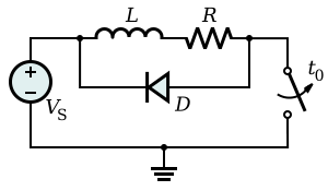
Of course our antenna doesn’t really care about high voltages, but this example helps explain how storing energy in fields is a real phenomena, causing real problems, prompting requisite solutions.
Smoking Gun
The EFHW mystery-current smoking-gun is found with the ability of the electric field to “store” the energy from the current. The current flows into a capacity represented by the E-field. Terman describes as much noting a parasitic capacitance in the parallel transmission line end fed dipole variation shown in figure 15 with the green addition to the dimension arrow highlighting my notion the high impedance feedpoint is actually within the half-wave antenna.
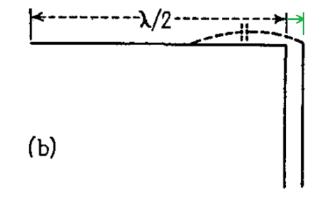
“In method (b), the termination of the transmission line is completed through the capacity from the open wire of the transmission line to the antenna, as shown dotted. In this arrangement, the antenna length must approximate a half wave length, and the transmission line adjustment must be such as to provide a voltage loop at the antenna termination of the line.”[9]
The understanding from WWII times is the current on the unconnected side of the parallel feed line is never quite zero since the parasitic capacitance gladly accepts the current to build up charge.
Conclusion
A discussion of end-fed antenna currents and “where they might go” is incomplete without considering the storage of energy in the induction fields of the antenna. If the currents from either side of the power source are equal in magnitude, the vastly higher voltage value of the “short” side explains the apparent inequality.
This hypothesis is likely true for cases where there is no red wire in figure 2 and the series coil has only an open terminal. Given the trend seen in the E-field strengths of figures 9 through 12, with no wire the voltage increase should be more dramatic and perhaps most difficult to accommodate. Keep your tongue off this spot while transmitting. This likely explains the benefit of adding a short length of wire to the open end – hence nudging the feed system away from the very tip of the dipole antenna.
There are those on The Zed and elsewhere who will never accept Maxwell’s displacement current as a valid explanation for wire-end-current in end fed dipole topologies. One quote concerning this article says “In this post we learn who does not understand parasitic current paths” highlighting the seemingly never ending quest for anything other than displacement current to explain why EFHW antennas work. Such partial understanding of antenna theory can be forgiven since the topic is not easy for beginners. Let’s be clear… this entire article exists not to understate parasitic currents, but to show they need not be present for a dipole, fed anywhere along its length, to function just fine. Parasitic currents to ground, feedline, etc. are purposely omitted to show they are not required.
Update June 2019 – Real Measurements
The following article shows some real measurements confirming the above.
Electrically isolated end-fed vs. center-fed dipole radiation
References
- “Merry Christmas to all the EFHW Common Mode Current and Everybody Else!” – QRZ.com
- “The dipole antenna, how industry defines it.” – hamradio.me
- “Kirchhoff’s circuit laws” – Wikipedia
- “EFHW LNR Precision EF-10/20/40MKII Examination” – hamradio.me
- “The End Fed Half Wave Antenna” – Steve Yates, AA5TB
- Griffith, B. Whitfield (1962). Radio-Electronic Transmission Fundamentals. New York, NY: McGraw Hill Book Company, Inc. pp. 322–323.
- Balanis, Constantine (1982). Antenna Theory. Harper & Row, Publishers, Inc. pp. 116–118. ISBN 0-06-040458-2.
- “Flyback diode” – Wikipedia
- Frederick Emmons Terman (1943). Radio Engineers Handbook. New York, NY: McGraw Hill Book Company, Inc. pp. 849–851.
- Griffith, B. Whitfield (1962). Radio-Electronic Transmission Fundamentals. New York, NY: McGraw Hill Book Company, Inc. pp. 318–320.
- Stutzman, Warren; Gary Thiele (1981). Antenna Theory and Design. New York, NY: John Wiley & Sons. pp 214-215.
quote:
Yes, I believe it too… 73 Danny E73M
BTW great analysis of an EFHW antenna
Agreed, nice work.
What FDTD software do you recommend?
MEEP is the one to try since it is free. The above was generated by a commercial product since this topic is of concern to our professional work.
Right.
An accurate model must be consistent with conservation.
Actually, the simplistic version of the end of the antenna used here is misleading at best and incorrect at its worst. Consider a matching network contained in a metal box. There is no radiation from within the box yet there IS parasitic capacitance and inductive coupling. In this situation the "radiator" is the 1/2 wave length of wire and the "box" and the matching network are all "matching network."
The current that you are having difficulty explaining away is simply the displacement current working against the earth, the metal box and the co-ax shield. Don't get carried away with calling it a "capacitor" though even if it can be modelled as one. You need to include a pseudoresistive element to account for the radiated losses AND a simple resistive element to deal with the conduction and imaginary component of the dielectric media (usually for air we take this to be zero but in wet areas or areas with vegetation in the near field this is not true). If it were truly modelable as a "capacitor" you would radiate NO power!
In short you need a counterpoise or a ground to generate a differential electric field and thus a manner to have an electric field to be orthogonal to the resultant magnetic field for there ot be an E X H for a propagation of energy away from the structure….
Hi. Here are some questions.
What's to prevent the displacement current interacting with the rest of the antenna?
Would the experiment outlined here… https://www.hamradio.me/antennas/electrically-iso…
…produce different results if it was moved far away from other objects, ground, etc. or show a varying effect depending on distance from them?