Can a dipole be fed at its end (or near end)?
No one argues a dipole cannot be fed at its center or even quite a bit off center. Some suggest it is impossible to feed a dipole at its end without some sort of “other” conductor to “push against.” My simulations suggest one can “push against” the opposite terminal of whatever power source exists at the end leaving it with very high voltage wrt the rest of the antenna system. Presented below is a test measuring the magnetic field strength near the dipole wire vs. position along the wire. I perform the test twice differing only in the position of the energy source.
The “ideal” dipole test setup
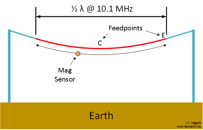
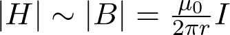
Figure 1 portrays the ideal test configuration. Non-conductive supports (blue) hold a dipole (red) trimmed for operation in the 30m amateur radio band. In actuality, I made two dipoles from yellow insulated lab wire, one with feedpoint midway (point C), the other with an LNR Precision transformer at the end (point E).
The “real” dipole test setup
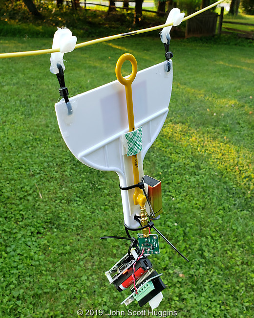
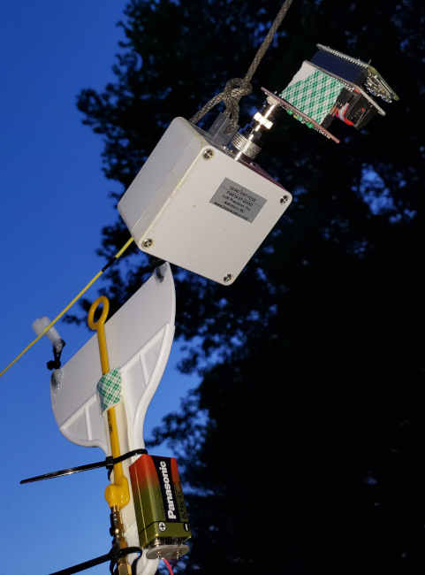
It’s springtime here in Virginia and nightly thunderstorms with the occasional tornado watch are the norm. Sometimes you have to sneak in a test wherever and whenever possible. Such was the case when I finally had an evening available to perform a quick test.
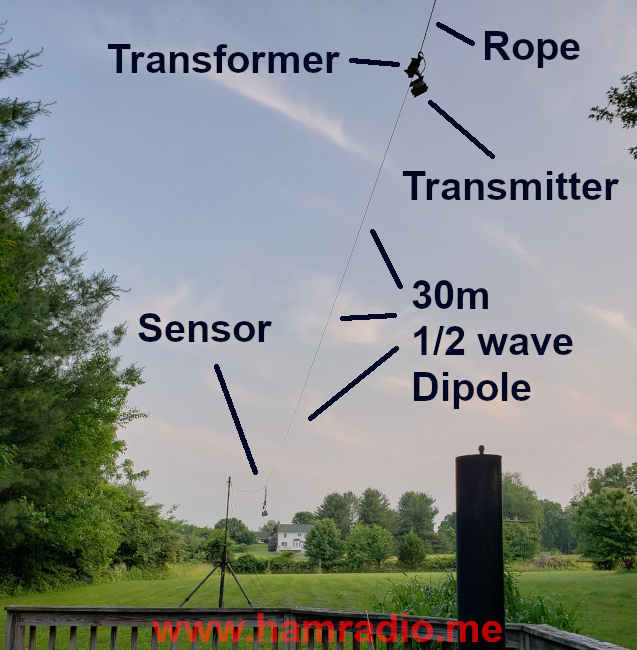
Yeah that’s my smoker just beyond the dipole’s end. The far support is a non-conductive fiberglass mast. The rear support, behind the photographer, is my house. Each yellow wire dipole has black markings at one foot intervals to provide quick guidance for sensor placement during tests.
The antennas under test
In a perfect world I would have one dipole wire for the 30m test with two feed positions. I instead made two antennas: one center-fed and one end-fed. I did perform S11 on both to trim for the 30m band. Unsurprisingly, both are the same length. The VSWR for the center-fed is under 1.5. The VSWR through the step-up transformer for the end-fed is also under 1.5.
Dipole testing electronics
If we are to test a dipole with no extra conductors, such as feedline, then we must place the same restrictions on the testing gear. Fortunately we live in the 21st century where battery operable tiny computers with WiFi built-in provide slick solutions.
Let’s introduce the active components used to energize the antenna and measure the magnetic field.
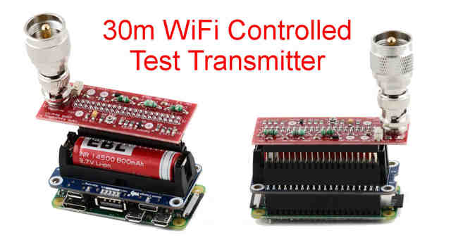
30m Transmitter Raspberry Pi assembly
A way to energize the dipole without any feedline was remarkably simple with the stack seen here.
From bottom to top…
- Raspberry Pi-Zero W with WiFi that works surprisingly well for its size (Attached to my interior WiFi at the other end of my house no problem).
- Spiffy 3 volt lithium power Hat to power the R-Pi.
- Header extender,
- TAPR 30m LPF and amplifier Hat.
In the above photo, the transmitter assembly connects directly to the center of the 30m dipole using a BNC-Banana adapter. With the TAPR 30m hat, the transmitter generates about 150 mW of power measured into 50 ohm load.
A bit of tape on the opposite side ensures the stack stays so.
More details available in my other article…
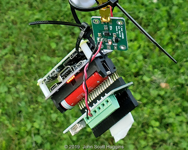
Some earlier photos of the transmitter
Here you see the transmitter held together with rubber bands. It is attached to the broadband LNR Precision transformer from their 10/20/40 product reviewed earlier in this end-fed configuration.

The recent purchase of a PL-259 to male BNC adapter (not easy to find) shortens the connection between the transmitter assembly and the transformer. It’s tight.
No wires. No transmission lines. Self powered. An antenna energized by this transmitter is as isolated as one can get.
Magnetic field Raspberry-Pi sensor assembly
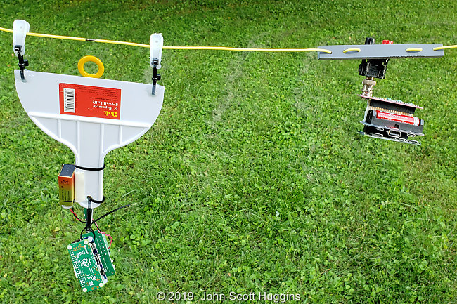
Allow me to introduce my little friend… Frankensensor.
This is what happens when you take the electronics described in an earlier article into an Ace hardware store for packaging ideas. Key electrical components top to bottom include:
- Honest to goodness passive magnetic sensor from Beehive Electronics (the yellow loop with wand).
- Logarithmic RF power to voltage converter (aka RSSI) and a 9V battery to power it.
- Raspberry Pi stack (details below) to measure the voltage and convey the readings via WiFi (no additional wires).
For structure we have:
- One 6″ disposable drywall knife modified with a couple of holes at the blade edges.
- Wire ties arranged upwards to a couple of curtain clips, or some such things, that hang on the antenna wire.
- More wire ties to ensure conductive wiring isn’t holding weight.
- A bunch of hot glue in key spots to keep the antenna clips pointing up.
- Some double-sided tape to keep the sensor wand always coplanar with the antenna wire (not that a few degrees would make much difference).
The goal is pretty simple… maintain the sensor loop the same distance from and orientation with the antenna wire and hold it there during any specific measurement. Indirectly sensing antenna current this way perturbs the antenna a bit less than a clamp-on ammeter… or so I suppose. It was easy enough to try.
This contraption isn’t my proudest moment in fabrication, but it works quite nicely.
Sensor Raspberry Pi stack
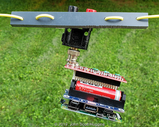
Zooming in a bit on the previous photo provides a better view of the active electronics.
The RF to voltage (RSSI) board hangs on the end of the sensor wand and has an LED to indicate power. It has a pair of wires to convey the measured voltage to the Raspberry Pi assembly that includes from bottom to top…
- 16 bit, four channel, A/D hat (only one channel used for this test),
- Header,
- Battery power hat using 3 volt lithium cell. The five LEDs indicate full charge,
- Raspberry Pi-Zero-W with built-in WiFi,
- Some tape to ensure it stays together.
The battery hat connects directly to the header of the Pi-Zero. The height of the battery hat precludes direct connection of the A/D requiring the use of the intermediate header.
All these components are readily available to anyone to replicate the test.
Pro-tip: The Pi-Zero will NOT boot if the power to the RF-to-voltage board is on and a voltage appears on the A/D. I have no idea why and it took a long time to puzzle through this issue. If you build one of these, just connect the 9V battery after booting the Pi-Zero.
More details in my other article…
The control point
With both Raspberry Pi computers booted and connected to my home WiFi, I shelled into each of them with my computer and monitored the transmit signal with a portable shortwave receiver.
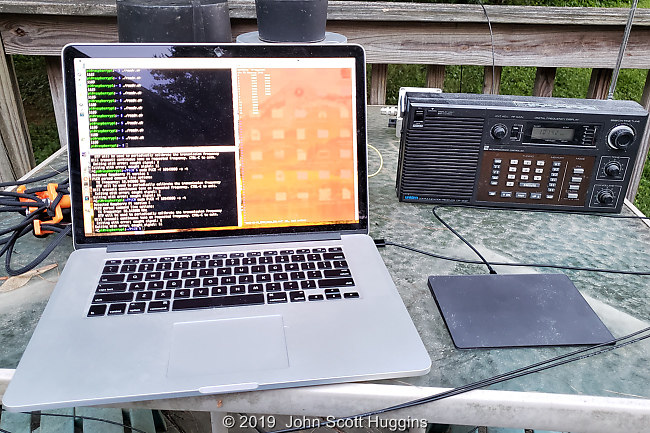
Click to open the view of the control windows below.

We have:
- Shell into the sensor R-Pi upper left showing various measurements in millivolts.
- Shell into the transmit R-Pi lower left using PiCW to generate the test signal on DIO4. The TAPR hat filters and amplifies this signal.
- Red shell with a text file editing session to record the millivolt measurements vs. sensor position.
Finally the result
Converting the millivolt readings to A/m requires a bit of math. We have the inverse and logarithmic nature of the RSSI module, the published formula from Beehive Electronics and then conversion to A/m. Here is a quick view of the math in the GNUplot command file.
# power-voltage Y=mX+b parameters of the AD8318 IC in the
# RSSI module as measured in lab by KX4O
m = -.024433333 #volts/dB (differs from -.025 V/dB data sheet value)
b = 26.7535 #dBm (differs from 20 dBm data sheet value)

# Inline conversion to Tesla per Beehive Electronics datasheet (for 10.1 MHz),
# then to A/m (x 797700) from the RSSI voltage.
plot [0:44] \
'2019-06-01_EFHW_Data_001.txt' using 1:((10**(($2/1000/m+b)/20-5.259))*797700)
'2019-06-01_CFHW_Data_001.txt' using 1:((10**(($2/1000/m+b)/20-5.259))*797700)
GNUplot rocks! That I happened to be within the scale and range for each component in this signal chain was dumb luck. Behold…
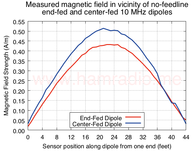
If we assume the strength of the magnetic field immediately around an antenna wire is proportional to the current at that point…
…you can clearly see the classic half-wave dipole current distribution.
Observations:
- Both the end-fed and center-fed antennas operate just fine without any additional conductors or feedlines.
- The end-fed energy is less than the center-fed. If you do the math, it emits about 1.6 dB less power than the center-fed.
- Given the small toroid size, the LNR Precision transformer is probably the reason for the small loss, but that’s just a guess.
- I have no explanation for the lower readings of the center-fed at 37-40 feet. Yeah they bother me too, but that’s life in Realville. This doesn’t detract from the overall message conveyed by the graph so I’ll file a copy of this perturbation under “dammit” and move on.
- Center-fed, end-fed (or “pretty darn close to end-fed” if you like), you can clearly see the dipole operates well from either feed point position.
Conclusions
I can find no reason to suggest a dipole cannot be fed anywhere along its length without aid of other conductors to “push against.” Simulations agree. Yeah the above graph reminds us there is a loss penalty to pay for a proper transformer to feed a dipole at its highest impedance point, but there’s nothing magical going on here. It just works.
As discussed here…
…potential problems lurk when you actually do attach a feedline although most feedline lengths are quite forgiving. The story continues to evolve on this web site…
https://www.hamradio.me/interests/efhw
…and may well forever. They key takeaway from this test is for owners and users of EFHW antennas to fret not what some folks have to say about their aerials and just use them with some confidence there is no bogeyman lurking to spoil their day.
Next steps
If my transformer efficiency guess above is true, later models with higher power ratings may shrink the difference. I have a later model higher power LNR transformer from their EF-QUAD product and another transformer from MyAntennas. Both are much much larger and heavier than the mostly QRP transformer used for this data. I will repeat the tests above with these two newer units to explore this topic a bit more.
UPDATE June 3, 2019
I did test the transformer from the LNR-QUAD. It has a more robust toroid within.
Let’s see what happened.
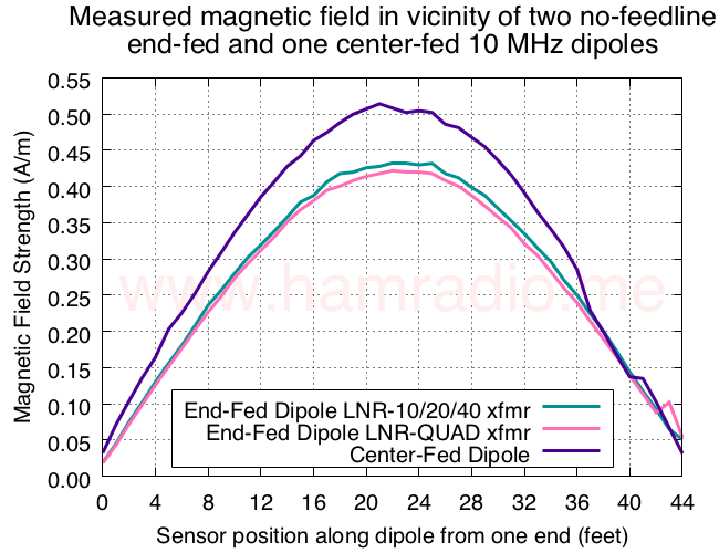
Well, the small step-up transformer from the LNR-10/20/40 EFHW and the larger transformer from the LNR-QUAD perform identically. Both are about 1.6 dB lower radiated power than the straight up center-fed dipole. I suppose the good news is the size of the toroid governs max power handling, but not efficiency.


Both LNR transformers have more insertion loss than MyAntennas.com MEF-330-1K you have… if you give it a try it will show less difference. More likely like 0.6dB instead 1.6dB with small LNR transformer.
73 Danny E73M
Roger that Danny. Your transformer is next.
Thank you for the article! However I don't believe that the experiment was completely fair. The center-fed dipole requires a 1:1 balun which you didn't use and which would have some losses as well as a end-fed dipole transformer does (although end-fed dipole requires an RFI choke too). Also according to Figure 1 the end-fed dipole was fed literally from the end which is also not right. In reality it needs a counterpoise 0.06-0.07 lambda, otherwise the reactive resistance is way too high. In other words it would be interesting to see an experiment that would be closer to real-world scenario: 1) a 1:1 balun for center-fed dipole 2) 0.06-0.07 lambda counterpoise + RFI choke for end-fed dipole. I got a feeling it may affect the results quite a bit. 73 de R2AUK
"The center-fed dipole requires a 1:1 balun which you didn't use" – A floating source such as that used in this experiment alleviates the need for a balun to ensure equal antenna currents as there is no feedline to complete for such currents. The element currents are equal by definition.
"Also according to Figure 1 the end-fed dipole was fed literally from the end which is also not right." – The test results confirm end-feeding works fine with the LNR transformers. That's the point of the test. I will also be testing with an extra wire just to see what happens, but it clearly functions without it.
Ok, I see. I thought your intention was to compare an effectiveness of a dipole vs EFHW. IMHO there is little use of conclusion that the EFHW with a LNR transformer functions. There is little doubt in that and you could just make a few QSOs using both antennas and make the same conclusion. No need in measuring field strength or anything.
A much more interesting experiment, since you have a proper equipment, would be to compare an effectiveness of both antennas, considering losses in all transformers / baluns / chokes required. But in this case besides transformers and chokes you definitely need a 0.06-0.07 lambda counterpoise (or a part of the feedline that would work as a counterpoise). Otherwise the antenna has a very high reactance which will make SWR depend on the length of the feedline, which is usually not something you want. 73 de R2AUK
"Ok, I see. I thought your intention was to compare an effectiveness of a dipole vs EFHW. IMHO there is little use of conclusion that the EFHW with a LNR transformer functions. There is little doubt in that and you could just make a few QSOs using both antennas and make the same conclusion. No need in measuring field strength or anything."
You must understand there are many people who don't think the EFHW can work without some sort of extra wires attached. I set out to prove it one way or the other with good measurements that avoid subjective ability to make a QSO or two. I'm thrilled you are among those who don't need such evidence, but many others do.
"dipole vs EFHW"
Just for clarity of definitions, both of the above are dipoles.
As I learned dipole means 2 poles. I also learned an antenna to radiate need two poles. Even a monopole has the second pole. If not a counterpoise than someting else will do the job. Remember you had problems with booting while RF was on.
I understand that you're comparing two 1/2 lambda antennas one center fed dipole and another, a lambda/2 monopole.
Could you explain why you thing both antennas are dipoles? Was not able to find this in Balanis or Kraus.
"Could you explain why you thing both antennas are dipoles?"
By definition… https://www.hamradio.me/antennas/definition-of-di…
I have seen similar seat of the pants results. I have three antenna supports (trees!) that I have used for a 130 foot piece of wire. I have fed it in the middle with 450 ohm line and a Johnson Matchbox, at end with 450 ohm line and a Johnson Matchbox and at the end with a Myantennas matching unit. All three configurations work the same as far as I can tell. The end fed gets the feedline out of my view of Pikes National Forest and requires no tuning when band changing.
Dave
Dipole is 2 poles end-fed is one pole.
Function, not form… https://www.hamradio.me/antennas/definition-of-di…
Mr. Hertz would be proud of you sir.
Actually I came to the conclusion that any 1/2 wavelength antenna is a Hertz antenna no matter where it is fed.
Center fed Hertz or End Fed Hertz… It matters not. it's a Hertz.
Marconi and his 1/4 wave things are a different animal. They need a counterpoise!
Thank you.
Very interesting. Everyone who claims that "you gotta have something to push against" are correct, but I wonder if they aren't missing something…..When the impedance you are trying to drive is so high (~2.5k – 3kohms), what you are "pushing against" doesn't need to be very low impedance at all. At 10MHz, even 5pF of stray capacitance (from the "ground" side of your floating transmitter) to earth ground would result in ~ 3dB loss. In fact, I wonder if much of the 1.6dB loss you see isn't transformer loss, but just voltage loss across the stray capacitance.
Your hypothesis is worthy of testing by way of repeating the same tests at much higher elevation. I have all the gear, but need volunteers to perform the testing in a valid way. I'm presenting the details to my local ARC in August and will hopefully stir up the troops to provide some manpower. Stay tuned.
As for "something to push against" keep in mind you can do so against an open end as well as short. That's what many people miss.
Re-reading this, I was too terse and my meaning could be easily misunderstood. Should have said: "At 10 MHz, a stray capacitance from the open end to ground of only 5pF would give an impedance to ground that is similar to the 2.5k of the antenna. The voltage at the transformer output would be divided between those two impedances, giving some signal loss. If the impedance of the antenna is mainly resistive, the impedances would appear in a quadrature relationship, giving around 3dB of loss (compared with an ideal counterpoise).
If you really want meaningful tests, you need to operate each antenna as it is designed to work. That is, each should have proper RF current choke, BALUN, and matching transformer with the same height above ground and transmission line loss. I suggest you use WSPRLite transmitters on each for many reasons I give in my presentation on measuring HF antenna performance. You can find a copy at: https://drive.google.com/drive/folders/182jXlJ9IF…. 73, Bill, K8TE
Bear in mind the tests above were to specifically verify if the EFHW with 49:1 transformer actually radiates with no extra gear, counterpoise or what have you as that was specifically the question at hand. Comparing resulting antenna current magnitude (via H-field magnitude) provides the evidence. However, further testing with the things you mention is certainly next on the list not for the sake of verifying a halfwave aerial with 49:1 (or so) transformer and independent CW transmitter can actually work, but to see what connections made to the system with feedline, etc. mess with the system's natural ability to function.
I do like the WSPRLite transmitters if they can be configured to produce a steady signal for testing. Other than for "hey it kinda works" experiments, WSPR is too inaccurate for any meaningful absolute measurements. This might change if the WSPR network reported the absolute signal level rather than S/N. Don't understand why they don't since the information is available. Oh well.
Great article. Thank you for taking the time to carry out the experiment and document it. All definitely in the spirit of ham radio. Think the RPi generator and measuring set up is excellent. One thing I am very curious about is what an additional test with a "counterpoise" (say 0.05 lambda) added to the EFHW would reveal? A plot of the results against the EFHW with no counterpoise would perhaps have shown if there is any significant benefit in terms of radiated power for counterpoise vs. no counterpoise? I realise this was not the aim of the test which successfully demonstrates that the counterpoiseless EFHW radiates perfectly well. However, it would maybe go someway towards settling the arguement?
I did repeat the experiment with an additional 0.05 WL wire…
https://www.hamradio.me/antennas/adding-0-05-wave…
It still works albeit with some small difference. I need to repeat all these tests again to see how repeatable they are. Plus I will find a volunteer to operate an Antenna/SDR some distance away to compare far field receive power. This to appease not AI3V, but those who might be listening to him.
What was the elevation of the dipole / end fed?
I tend to agree with Dan, that the bulk of your trasmitter couples to ground capacitively.
Thanks for a great writeup, it must have taken you a considerable amount of effort to do the experiments.
Thanks for recognizing the effort. It did take some work, but is a labor of love for this topic.
The antenna was just above head (6' 2") height to facilitate using my outreached arms to get this conceptual test done. It was just as much about testing the new fangled gear as well as seeing some sort of preliminary result from the EFHW hypothesis. I got both, but now certainly need to redo the test with the dipole much higher using my local ARC for labor. It would have happened last weekend, but for Spring winds and Pandemic. 🙁
An "Aha!" moment. Take a dipole, any dipole. Drive it from the center. Now we want to measure the RF voltage and current at an end. I imagine that we would want to use the same type of transformer setup that we have used in an EFHW, transforming the high voltage and low current to make the measurements on a length of coax down at the measurement instrumentation .
Now take any dipole, this time driven from one end with the transformer scheme as in this article. Say we we want to measure the RF voltage and current at the dipole center. I imagine that we would want to use a setup like we would use in a "conventional" center-fed dipole driving scheme, thus transforming the high current and low voltage to make the measurements, with a common mode choke and a length of coax, down at the instrumentation end of the coax.
I think the transformation of the impedances in both cases will result in essentially the same results: the antenna can be driven and it will radiate all of the power presented to it (less any line or transformer loss).
If a person believes that a counterpoise of 1/4 wavelength, or of some arbitrary length of feedline coax shield is required for an EFHW to work, that person must also believe that the voltage and current of a dipole cannot be measured at the end without such an artifice as a "counterpoise.)
Seems logical.
Great work really enjoyed…
AA5TB presented some methods used to match a rig’s 50 ohm output to an EFHW and he included extensive discussion of counterpoise as he understands it. Another matching method was once presented by KB6NU (20 meter L-C network named matchbox). Both of these can be found by internet search. Most likely you have used one of the above methods. The reason I bring this up is that the matchbox method did not seem to require any counterpoise in it’s description. It would be interesting to compare experimental magnetic field results when using the matchbox technique verses best method as described by AA5TB to see if differences these matching methods impact the measured EFHW performance.
It's my understanding the monoband end fed antennas use such an LC approach…
http://www.vibroplex.com/contents/en-us/d9177.htm…
It's on my list to test with the same setup.
Yep – In my case the EFHW antennas I put up this year came from: https://www.radiowavz.com/product/end-fed-half-wa…
My ohm meter confirms a direct path from center of SO-239 and antenna wire of my EFHW. I think internal matching circuit is similar to one described here: https://www.kb6nu.com › wp-content › uploads › 2012 › 08 › Endfed20.pdf
so if a 1/2 wave dipole is the reference standard, dbd, where would a T2l2 end fed dipole measure up gain wise? when in a vertical position are there readiation patterns the same?
Thanks
We have to be a little extra careful when we try to prove people like Kirchoff and others wrong. We have to understand what we are doing better than countless people before have understood what they were doing, some of whom have electrical laws named after them.
We also have to understand common mode generation well, something almost nobody seems to actually do.
A thin low loss half wave, depending on height and surroundings, is about 50-100 ohms at the center. Each half is 25-50 ohms in common mode, and the center feed puts them in series. Displacement currents allow current taper and current to flow to the end. Each side of the dipole is coupled by that electric energy storage field.
How we leave that field with a feedline has a whole lot to do with the common mode, since it is the longitudinal voltage along a conductor that causes current flow. If we leave straight down the center the fields are balanced. The troublesome common mode feedline excitation comes when that field is not symmetrical and drives one transmission line conductor more than another. With a balanced line in the center, both conductors are equally exposed and the antenna is not responsible for any longitudinal excitation of the line. With coax one conductor is hidden and the shield is exposed, so the shield is driven by the dissimilarity in feed point voltages. One is hidden from the world in the cable center, but the shield is on the outside and has a path driven by the feedpoint voltage.
As we move closer and closer to the end this problem is worse. An OCF antenna becomes very difficult to tame. The closer to the end, the worse this problem becomes. We fix it at the end with an infinite counterpoise. Testing without the feedline doesn't prove anything, there is nothing there to have common mode.
One might then wonder how the antenna is excited. The junk hanging on the end and anything around that junk actually becomes the counterpoise. If we are on 10MHz the impedance of just 20pF is 796 ohms. We all know, or we should know if we are smarter than the old masters, that an isolated single terminal sphere of 10 inches is 14pF.
That little bit of transmitter junk hanging on the end might be a 1000-2000 ohms common mode, but whatever it is we can be certain it is not near infinite. If it was infinite as a ground or counterpoise, you would be unable to feed the antenna. We also know the reactance part of that capacitance is lossless.
If that end-fed impedance is 8,000 ohms, which is not an unreasonable value for a low-loss thin conductor of 1/2 wave, we now have a differential feed impedance of that 8000 plus the mass impedance of the electrical junk, or maybe 10K ohms. Of course, these numbers could be a whole lot lower or maybe even a little bit higher.
The important takeaway is it does not take much of a counterpoise to feed thousands of ohms.
One should know how the antenna system really works before calling out Kirchoff or others as buffoons. Then a proper test could be done.
I find nothing about the results surprising:
1.) There is no feedline, so there is no common mode feedline problem
2.) The transmitter or any junk hanging on the end is not infinitely small, so it has a definite finite common mode impedance
3.) The end impedance of the wire is high, 4K to 8k ohms or so probably. It doesn't take but a few pF of counterpoise to feed that and the reactive part is lossless
I'm not sure what was proven. This test does not surprise me. The issue with an end fed is the common mode current on the feedline when it does not have a low impedance counterpoise, just like any off-center fed antenna has as an issue. The common mode results being an impedance ratio problem of the feedline common mode Z compared to voltage driving the feedline up at the antenna end, and the standing waves of that common mode. We eliminate the feedline and a pretty small counterpoise can work well. I fully expect the results shown.
The only thing that surprises me is I expect anyone trying to disprove rock-solid mature science would have done a meaningful test.
My money is on the electromagnetic eggheads. Even in the context of AC, Kirchhoff ('hh' by the way) rules the roost.
Why not year the third case, where you hang a little "counterpoise" off the secondary when end feeding to show whether it makes any difference?
Might be helpful to choke off the rpi, and explicitly test no counterpoise vs counterpoise to better satisfy the haters.
"Why not year the third case, where you hang a little "counterpoise" off the secondary when end feeding to show whether it makes any difference?"
That's a good point and I think most agree this works. I was exploring the notion the EFHW doesn't require it so that's where I focused my limited time. Maybe on the next run I'll add this test.
"Might be helpful to choke off the rpi, and explicitly test no counterpoise vs counterpoise to better satisfy the haters."
I don't disagree. Keeping the R-Pi small with respect to wavelength and having no extra wires addressed the need to show the dipole works alone whereever you feed it. This test caused one doubter to suggest I faked the data. There are limits to what I will do to convince those who cannot be convinced. I'm quite happy to let others digest the test data and make up their own minds. There is also the problem of inserting a high impedance with a choke at a logical high impedance point in the antenna system… the result is minimal choking when the impedances are similar.