Preface to Velocity Factor Experiment
In the Part 1 of this series I discuss various attributes concerning the use of Baluns especially in the VHF/UHF bands. Reviewing:
- I point out other web sites with excellent tutorials on why and where to use Baluns in VHF work.
- Two particular Balun styles come up strong: 1:1 Coaxial Cable Balun and the Pawsey Stub otherwise known as 1:1 Folded Balun. Each Balun’s topologies are shown in Figures 1 and 2.
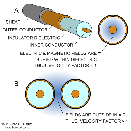
- I highlight the mistaken, I believe, assertion one should adjust the Pawsey Stub’s length by the amount of the coaxial cable velocity factor. Figure 3 shows why I think the Pawsey Stub length does not need as drastic a reduction in length as you might do for stubs that contain the electric and magnetic fields within their structure.
- Finally, I say I will prove my assertion the Pawsey Stub is electrically a 1/4 wave in free space or close.
What follows is the experiment which provides proof Velocity Factor of Coaxial Cables does not apply to cables used simply as a wire in parallel with another wire.
Velocity Factor Balun Experiment
The two Baluns are an excellent pair to compare. The Coaxial Cable Balun is just two transmission lines tied together one 1/4 wavelength long, the other 3/4 wavelength long. In this case the electric and magnetic fields are entirely within the dielectric material. Thus the velocity factor adjustment should apply. The Pawsey Stub relies entirely on becoming a parallel transmission line with the feedline coax. Its fields are entirely outside the structure of the coax.
I built the two baluns using some RG316 coax. My target frequency for both is 300 MHz. I cut pieces with no corrections applied to see how the frequency changes.
Coaxial Cable Balun Measurement
The Coaxial Cable Balun has the following dimensions based on calculations…
- 1/4 wave section = 300m/s / 300 MHz * .25 = 25cm ~ 9.8 inches
- 3/4 wave section = 300m/s / 300 MHz * .75 = 75cm ~ 29.5 inches
I simply cut two pieces of coax to the above lengths and added a third with an SMA connector for the feed line.
Figure 4 shows the Coaxial Cable Balun with a 50 ohm resistance at the balanced feed point.
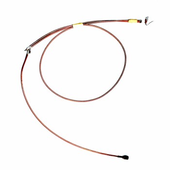
With the resistance at the feedpoint, the Balun should show some very obvious frequency dependence on a Return Loss or SWR plot. Because this is the case where the published coax Velocity factor does apply, the target frequency of 300 MHz should be lowered by .695 or about 208 MHz. Given that I flayed the coax shield and center, thereby reducing some of the coaxial cable length, the actual frequency should be a little higher.
Figure 5 shows what happens when I connect the Coaxial Cable Balun to the VNA…
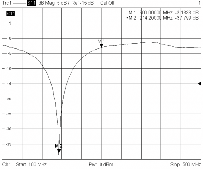
Wow the 214 MHz pretty much confirms that Velocity Factor is well in play for this style of Balun.
Folded Balun – Pawsey Stub Measurement
Now let’s try the Pawsey Stub. The only critical dimension is the stub length.
- 1/4 wave section = 300m/s / 300 MHz * .25 = 25cm ~ 9.8 inches
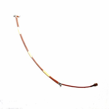
Once again, my trimming slightly shortens the actual mechanical length to about 23cm ~ 9 inches which raises the free space frequency north of 320 MHz. Figure 6 shows my test unit with 50 ohms at the feed point.
What’s the prediction here? If you listen to the web sites which suggest coax cable VF applies, the frequency will be between 210 and 230 MHz. If I am right and this is free space, or very close to free space, then the frequency should be something above 300 MHz, or since I made mine a bit short, something above 320 MHz.. Let’s see the Return Loss plot…
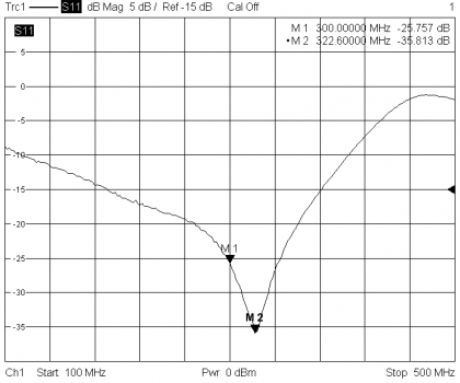
Bulls Eye!!!!
This strongly suggests the lengths of external stubs, like the Pawsey Stub (or any Folded Balun variant), should be calculated using free space wavelengths without corrections for published coax Velocity Factor.
The thing is, this has been the case in the ARRL Antenna book for many many years. The later editions never suggest to apply velocity factor to external stub calculations and the 13th edition specifically says VF does not apply.
Interference from Nearby Objects – an Additional Observation
Testing of the above two Baluns revealed an interesting behavior. The 1:1 Coaxial Cable Balun was immune to effects from handling during the test. The Pawsey Stub was very sensitive to touch or even being close to the stub portion. This evidence correlates well with the measurements suggesting the Pawsey Stub’s electric and magnetic fields are, at least some if not entirely, outside the realm of any dielectric material.
Conclusion
It is a good thing Amateur Radio Operators know about transmission line Velocity Factor specifications. Without this knowledge you would be cutting stubs incorrectly. However, some Amateurs assume that just because a piece of coax is used for a stub, Velocity Factor applies. The key to understanding when it does and when it doesn’t is found by following the electric and magnetic fields. Where are they? Are they inside the coax or outside between pieces of coax? If inside, apply VF. If outside assume freespace with a little loading by the coaxial sheath.
Measure, but verify…
This experiment relies on some crude cutting of cable lengths and assumed values of Velocity Factor. Potential sources of error include:
- Cable End Trimming – Source for my slight errors above.
- Coax Velocity Factor not what the manufacturer says – When you do need to know VF, it might be a bit off especially with lower quality coax. To date, however, I have not seen coax velocity factor off by more than a couple percent. The Pawsey Stub is certainly not a way to measure VF of coaxial cable.
- Freespace not quite freespace – Even the best air gap transmission line has some dielectric material in the fields – VF values of 0.95 are common even with parallel transmission ladder line.
Don’t Blame the Coax
A little research into the literature goes a long way towards understanding how a Folded Balun (or Pawsey Stub if you like) works. A simple hand-grab test of the Folded Balun that results in changing SWR or Return Loss instantly reveals external fields outside the realm of the coax dielectric… thus, coaxial cable VF rating does not apply. Lacking this understanding, an all too often quick assumption is to blame the manufacturer of the coax for poor control of VF during manufacture.
So what does this suggest? If you are going to the trouble to make something as critical as a Balun for your Yagi antenna, electrically measure each cable with your SWR meter or VNA to ensure you are spot on the frequency of choice.
This was an interesting test. I am now so interested in Baluns, I will focus on posts for each type in the near future.
Thanks for reading.
John

The vf to apply to the Pawsey stub is that of the pair of coax lines as a two wire open line. For example, I have measured two RG6 quad shield lines bound next to each other to have vf around 0.7… Owen
Generally true Owen. The various dielectrics surrounding the pair cause enough variation to require measurement case by case unfortunately.
I'm building a coaxial collinear vertical array using transposed halfwave sections of coax. (H. A Wheeler IEEE 1956) I was considering using a Pawsey stub at the feedpoint but wondering if the array would be better decoupled with a 1:1 1/4, 3/4 balun. Any comment?
Based on his tests, we could replace the coaxial cable Pawsey Stub by a single wire in parallel? It would not be necessary to apply the velocity factor? Or maybe 0.95 as the velocity factor? Thank you!
Yes the parallel stub can be a cylindrical conductor about the same size as the coaxial cable. I use exactly this for a Pawsey stub for my 1 GHz test antenna shown in figure 3 of this article…
Have your J-pole and ground it too
This emphasizes the point the Pawsey stub (aka Folded Balun) functions with external fields that have absolutely nothing to do with the insides of the coaxial cable.
Yes the parallel conductor can be solid, hollow or whatever. Only the external conductive surface area, in combination with the outside of the parallel coaxial cable makes up what is essentially a parallel transmission line shorted a quarter wavelength from the antenna feed point. Since there are dielectric materials (coax sheath, etc.) in the fields between each conductor, the resulting velocity factor can be very hard to calculate. I've found the only practical way to make a functional coaxial cable folded balun is to cut and measure until peak performance is found.
Hi guys
Very interesting reading, how does this test handle a "through" boom as in the G0KSC design? – one of the pictures show just a standard insuleted copper wire going paralell with the feed coax through the boom connecting a quarter wavelenght back on the feedline shield and grounding to the boom there.
One can wonder about the in that case what happens with the magnetic field surrounding this "stub" wire passing through tho aluminium boom itself, also what it ev. does to power handling of the design, wiregauge? Insulation thickness?
Anyone had any experience about this matter?
/ Anders
SM7HCE
Hello Anders,
You have the right instincts about thinking of the folded balun as a piece of parallel transmission line shorted at one end resulting in a high, choking, impedance at the other end. This leaves us with strong magnetic fields at the higher current end and, just as important, a strong electric field at the low current, high voltage end. Any conductor or dielectric present near the folded balun will affect it measurably. A simple hand-wave test will confirm this behavior. Passing such a thing next to or through an aluminum boom spoils its function.
John
Fine article! Thank you!
Can you comment on why the Pawsey balun has much greater bandwidth?
The likely reason is the longer piece of coax in the coaxial balun, the 3/4 wave piece, is naturally more narrow because of its length.