Selecting the first ferrite to examine
This is a summary of the various ferrites we will examine over time, but only one can be the first for close up inspection.

The immediate goal is to improve the 70cm performance of the N9TAX ladderline J antenna. The ferrite in TAX’s design does a pretty decent job for VHF, but the “61 cyl” has a slight edge at the higher band. The Fair-Rite 2661480002 Type 61 ferrite wins for first look… let’s continue.
The Fair-Rite Type 61 Ferrite Slide-on Choke
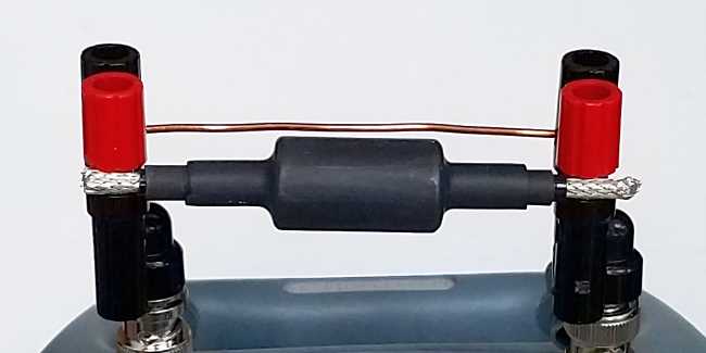
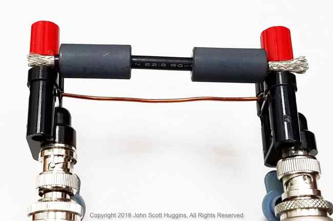
Figure 2 happens to show two type 61 chokes in series on the same test jig seen in the introductory article.
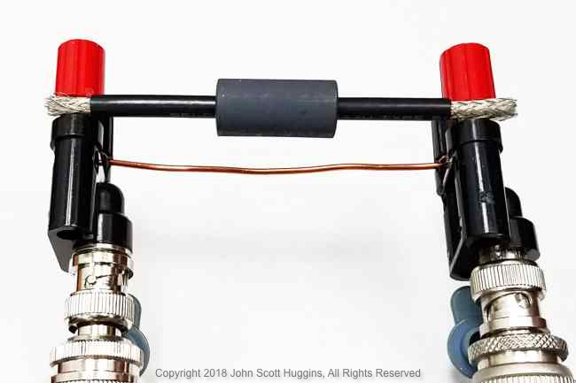
One Type 61 ferrite
Three tests were done with one ferrite in three positions: left, center and right. This isn’t really saying much in a test jig like this, but it was so easy to try, why not. Figure 3 highlights the positioning of the single ferrite. There isn’t a need to show the ferrite in the left position so no photo was taken… it’s symmetrical with the right position of figure 4.
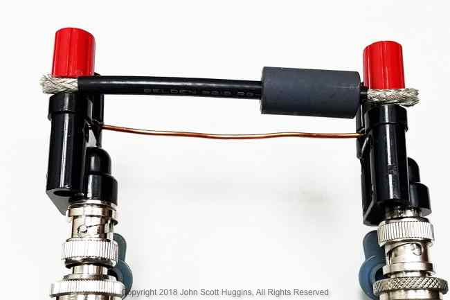
Two Type 61 ferrites
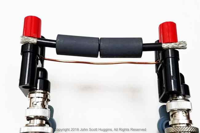
Figure 5 and 6 show ferrite positions for two tests with chokes in series.

Fair-Rite Type 61 ferrite S21 data
In this 50 ohm system figure 7 reveals the power “lost” due to the addition of the type 61 ferrite chokes in the various configurations. It is important to remember this is relative power lost so -3 dB = half power, -10 dB = 1/10th power, etc.

All the single ferrite tests, positioned right, center and left, overlap almost precisely with a little bit of divergence at the highest frequencies.
The double ferrite tests reveal marked improvement overall with a little over 4 dB less power making it past the coax ferrite chokes. The two double choke plots overlap quite well, but begin to show an advantage at the higher frequencies where the two ferrites are positioned shoulder to shoulder. The 400 MHz and above choking advantage over a single ferrite widens to just over 5 dB with two ferrites in series.
Fair-Rite 2661480002 ferrite current percentage derived data
Assuming a 50 ohm system, figure 8 portrays the relative percentage of current allowed through by the five scenarios.

Remembering that current is the square-root of power, the relative choking benefit in amperage is a less power. Since antenna folks worry about “choking that big ol’ bad common mode current,” I suppose this is a reasonable way to portray the choke benefit.
Observations
Adding multiple ferrites in series significantly enhances the ability to thwart common mode current. Still 20% of the possible current makes it past these deterrents. Whether this is enough to be a problem is a system level question left to the antenna/feed/mounting designer. The goal of placing ferrites as chokes it to present a sufficiently high impedance to “reflect” the power (current) back to the antenna so the chokes don’t absorb the power and convert to heat. It’s clear we have improved the choking capability with an extra ferrite, but with 20% current still making its way through, I have to think we may well be short of the desired “reflection” goal.
One of the primary tenants expressed by Jim Brown (K9YC) in his RFI guide is the notion one should “lump” high impedance in as little distance as possible to ensure you aren’t dissipating power in your choke system. The shoulder to shoulder chokes suggest this is true for the higher frequencies with the data above. The best approach to achieve this is to wind multiple turns of the coax through a toroid ferrite with the goal of presenting a high impedance with as little reactance as possible. That is the easy answer, but for now we will focus on single “turn” chokes in series for the cases where a large multi-turn approach isn’t practical.
Conclusion
There’s not much to say here. These tests merely reveal what most of us know. Chokes choke and more chokes choke more. The type 61 material does seem to provide good capabilities for the entire VHF band. Putting two in series helps the UHF performance around the 70cm band considerably with about 5-6 dB (power) improvement over the 4 dB in the VHF area.
