Baluns
I’ve not had to think about baluns very much until the birth of the Asymmetrical Hatted Vertical Dipole (AHVD) antenna. In truth I’ve been successful avoiding the need for a choke on my version of the Loop Fed 6m Beam and the 40m Mastless Dipole. I have no such luck with my AHVD. As discussed in my previous article, this offset fed antenna will do its level best to force currents down your feedline. It’s the cost one has to pay to use this antenna.
During initial tests of my AHVD “Speaker Stand” Prototype I tried several baluns including this one from DX Engineering. It did work, but I did notice some variability in Return Loss readings correlating with my touching the meter. This is a surefire sign of currents, however small, making their way down the outside of the coax. So the DXE balun does the job, but not perfectly at 20-10m. Improvement is possible by tailoring a choke just for the upper part of the HF band.
Guidance on Choke Baluns
I’m a regular reader of Jim Brown’s guide to Ferrites and Baluns [1]. This PDF file is 66 pages of great info including knowledge of how and when to use the various ferrite materials and why. My favorite part is Chapter 7 with recipes for solutions based on different coaxial cable diameters and choke frequency range. My RG316 is small enough to use Jim’s bifilar winding guide on page 37. A summary of the recipes can be found in this shorthand winding chart.
The AHVD Antenna needs a choke
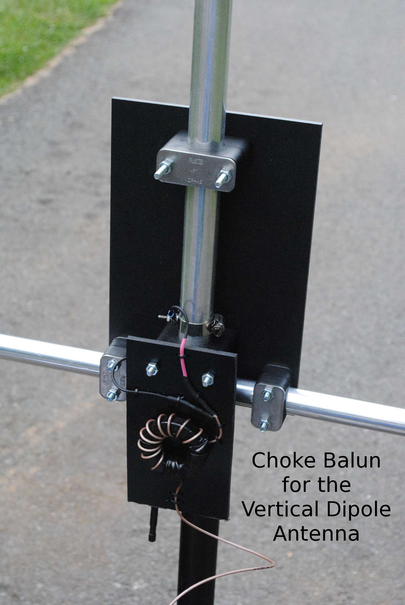
The frequency range for my AHVD antenna is 20-10m suggesting to wind 12 turns of the coax around a type 31 or 43 toroid. That’s just what I did. Here is a picture at the AHVD feedpoint…
Jim’s document includes many graphs showing the real and imaginary portions of choke impedance for his various frequency specific configurations. Jim’s advice is spot on and I did begin to measure these values. However, my VNA wasn’t giving results I could trust so I turned my attention to measuring the more reliable attenuation values. I used a calibrated VNA setup to measure S21 attenuation.
Wire Toroid Choke Balun Test
My first test observes the results of winding progressively more turns of #14 wire around a 2.4 inch type 43 toroid core.
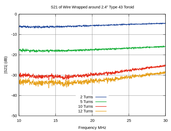
More turns… more attenuation and from 10 – 30 MHz as well. A welcome confirmation of Jim’s recipe.
Coaxial Toroid Choke Balun Test
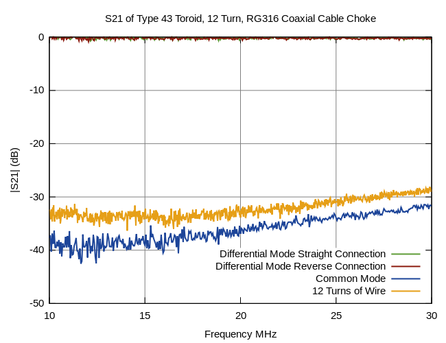
Armed with this happy find, I wound another #43 toroid with 12 turns of RG316 coax spending extra time on dressing the turns evenly. I put this on the test jig to examine the following:
- Differential mode S21 of the coax from one end to the next,
- Differential mode S21 of the coax from one end to the next with the connections on one end reversed,
- Common mode S21 of the coax treating the shield just like the #14 wire from the previous tests.
The 12 turn #14 wire plot from the previous graph is shown for comparison.
You can click the graph above for a better view.
The blue trace indicates the toroid choke is doing a very good job of preventing common mode current flowing through the windings. Surprisingly, the coax attenuation measured a bit better than the #14 wire. To be honest, even though this is a well calibrated setup, the error range of the yellow and blue traces are likely to be a few dB. That said the 12 turn RG316 coaxial choke does a very admirable job.
Now let’s look at the differential plots. A choke should only have an effect on common currents and leave differential currents free to flow through. Indeed, any coaxial choke balun will still be a piece of coax to the desired signal and that’s the case here in the green trace. If you take a piece of coax and reverse the connections at one end, you will short the signal to ground. As you can see in the red trace, the choke completely isolates the ends from each other such that it doesn’t matter which way you connect the end. With normal or reverse connections, the differential mode attenuation is nearly zero dB. If you can’t find the red or green trace, they are hugging the zero dB line at the top of the graph.
To put it bluntly, this choke balun works fantastic.
Coax Choke Balun in use
When I replaced the DXE balun with this one and performed the same “hand” test, I could not detect any changes to the meter readings at all. This suggests the choke isolates the feedline more than adequate.
Thank you Jim, K9YC, for your handy guide. It works.
References
- Brown, J. (K9YC), “A Ham’s Guide to RFI, Ferrites, Baluns, and Audio Interfacing.” Audio Systems Group, Inc., 2010. Retrieved July 30, 2013.


Hello, actually my measurements show that 12 Turns RG316 on F240-43 peaks at 28,8MHz with Zcm of 10.2 kOhms while 14 Turns brings it down to 20.5Mhz with Zcm of 13.5kOhms.
I love the RG316, it will take a lot of power up to 20m band.
73 Danny Horvat, E73M