My G3TXQ Hex Beam antenna continues to evolve. You can click on the Tag for hexbeam to find past posts about this project.
One thing I never liked about any hexbeam is the center post. All the various offerings, be they Traffie, K4KIO or others, pretty much make the hexbeam “the thing” that must be on top of your mast or tower. The center post is either non-conductive and not very strong or is conductive and part of the feedline system. Still others offer driver element feed systems that may be clamped to the center mast, but I don’t yet know if the mast may be conductive.
Add to this the desire to place other antennas above the hex beam (VHF beams for example) and to build in a little capability to properly handle lightning energies.
Don’t get me wrong, the above designs get the job done, but do so without regard for other antennas and lightning safety concerns.
So… a few must have features came about to include…
- Center mast shall be conductive to best conduct lightning from top to beneath the beam hub,
- Center mast shall be one continuous piece of material from rotor, to thrust bearing, through the spreader hub, to the spreader rope connections and above,
- A small antenna, compatible with the hex elements, shall be placed above the hex on this mast.
A few concerns include:
- The conductive mast shall not interfere with the operation of the hexbeam and its driven element feed points.
- Metal mast shall have sufficient tensile and compressive strength to survive the stresses of full wind loading.
- Mast shall be long enough to provide two point suspension (thrust bearing and rotor) beneath the hexbeam hub.
- Mast shall be long enough to provide mounting point for VHF beam high enough to not interfere with the hexbeam.
- Mast material shall be galvanically compatible with the aluminum spreader hub, thrust bearing and rotor.
- To protect the hex wire elements from lightning, the top of mast should be high enough to preferentially entice the strike leader of a lightning stroke using the 150 foot radius rule.
- The VHF Beam shall not electrically interfere with the hex beam or vice-versa.
Hex Beam Mast Galvanic Compatibility
The Galvanic issue was most easily solved by simply using the same material as most of the rest of my components… aluminum. The stainless steel hardware used throughout has some issues with aluminum, but what are you going to do… you have to fasten it with something.
Hex Beam Aluminum Mast Specifications
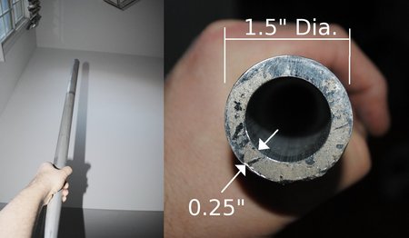
The maximum diameter of the aluminum mast is set by the throat of the DX Engineering Hex Spreader Hub assembly to just over 1.5 inches and by the TB-105 bearing at exactly 1.5 inches (with some encouragement from a Dremel tool). The longest aluminum mast I could purchase without using expensive freight shipping is 8 feet. I plugged this data along with values for antenna area, wind speed and aluminum characteristics into the…
…to find I need an aluminum mast with 1/4 inch wall. Believe me, I did over estimate on the side of safety, but the expense was not tremendously increased to my surprise.
A purchase from Penninger Radio scored the 8 foot, 1.5 inch diameter, 1/4 inch wall, mast (shown below) to my doorstep via UPS. The UPS shipping is a very significant savings in cost.
Replace Hex Beam Center Post with Aluminum
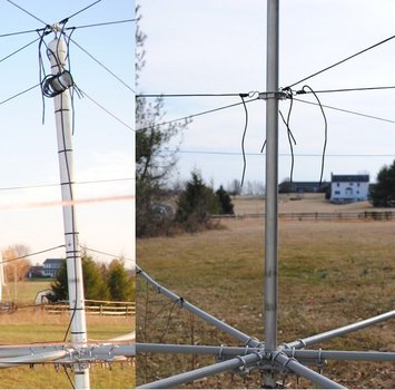
The photo below shows the original field proven PVC center post on the left with its replacement on the right.
Note the PVC is certainly not capable of staying straight if the hex beam spreader ropes are not in balance. The aluminum mast holds 1, 2, 3 or any combination of spreader ropes with absolutely no mast bending. Nice!
Here is a closeup of the new aluminum spreader rope hub custom made by a friend of mine.
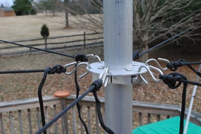
It clamps onto the mast and allows unlimited positioning up and down. Think of this as a glorified guy ring, but with six holes rather than three or four.
The Assembly
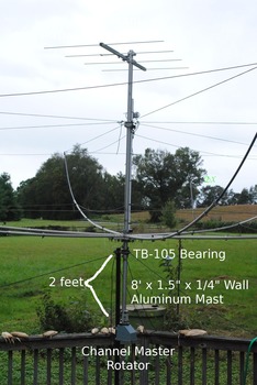
The photo below shows how all this goes together…
It’s reasonably obvious how the hexbeam’s new backbone mast makes for a much stronger assembly. What was originally a PVC center post is now thick aluminum from top to bottom.
What about shorting the Hex Beam feeders?
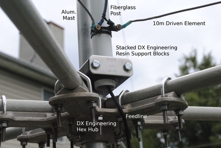
My hexbeam feed system is the traditional method where element wires are bolted onto threaded fittings which are attached to a non-conductive pipe. Feed interconnections are then made using the usual coaxial interconnects terminating into the top through a balun/choke. Obviously I can’t attach the wires to the aluminum mast. Many design possibilities exist to solve this, but, in the end, DX Engineering Resin Blocks came to the rescue.
Don’t confuse this aluminum mast spine with the metal coaxial feeder used in the K4KIO version of the BBHB. That nice system will likely suffer if you connect anything conductive to it.
There are a hundred uses for these beam building resin blocks and now there are one hundred and one. I used two sets back to back for the 1.5 inch mast and slightly smaller fiberglass feed post. It just so happened these two resin block sizes share the same mounting hole locations. Some long bolts are all I needed to make for a neat and sturdy joining of these two parallel pipes.
You can see I use wire ties with screw eyelets for securing the antenna elements to the feed line sections. It may be I could attach this directly to the aluminum mast since there is no electrical connection between elements and mast. However, I did not want to introduce capacitive/inductive interactions of the coaxial cable pieces with the mast just yet. Some time ago, I did do some real tests of the feed line system with a metal conductor waved in and around the hexbeam and did find some, but not much, sensitivity to the handheld metal pipe; I only saw an interaction when the pipe was within an inch or so. For this and other reasons I added the parallel fiberglass pole for the feed system to keep it well away from the aluminum mast for peace of mind. I’m quite sure there are better approaches.
Four Element VHF Yagi and Hex Beam Interactions
The candidate VHF Beam is quite small. EZNEC simulations confirm little to no electrical interaction between the hexbeam, the mast and the VHF beam (with its boom). So far real tests agree with predictions. I did note VHF beams with longer booms did interact with the hexbeam elements so this short beam keeps things compatible and makes good use of height real estate.
Hex Beam Lightning Considerations
To be honest, the center mast needs more height to ensure protection for the lower elements. However, I can attach an air terminal to the top of the aluminum mast to provide this height. This research is ongoing.
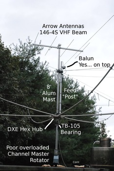
Final view
This is another view of the completed assembly with some notes…
The only thing left to do is get this thing up on a tower or mast, but that’s for another post.

Have you noticed any change in your antenna due to the grounded metal tube running through the elements?
No changes noticed… both in simulation and in practice. This isn't really any different than any horizontal Yagi-Uda mounted on a vertical mast.