Introduction
Welcome to the dissection and examination of the, formally Par Electronics, LNR Precision EF-10/20/40 MKII Multi-band Portable HF Antenna with its end-fed half-wave approach.
Background
I love participating in outdoor ham activities be they Field Day, Appalachian Trail Golden Packet, etc. Summits on the Air (SOTA) is another activity I helped organize (in Virginia). Participation must wait for procurement of proper gear.
Objective
Procure portable Radio and Antenna and participate in SOTA soonest and 1B Field Day eventually.
The choice of radio is for another post, but for a whole lot of reasons I think I will settle on an Elecraft K2 QRP model.
Portable antennas for the backpack include a wide variety of dipoles, long-wires, and end fed possibilities. I am an antenna designer by trade, but the topic of end fed antennas is relatively new to me; I wanted to learn more.
One valuable resource is AA5TB’s web page titled The End Fed Half Wave Antenna. The basic premise is to feed a half-wave antenna at its high impedance end using some form of impedance converter referenced to a counterpoise.
More information is found on the various outdoor ham radio email reflectors and other social sites. Most agree on the basic techniques of converting impedances. There is sharp disagreement on the need for a counterpoise. It appears the devil is in the details.
There are many cookbook designs for end fed dipoles. However, I wondered if commercial end fed antennas were available.
Commercial End Fed Antenna
After hearing many good things about the Par Electronics EndFedz Antenna product line I decided to see for myself what these aerials are all about.
Dale Parfitt, W4OP, appears to be the main designer of the entire EndFedz Line. Mr. Parfitt has a good resume of achievements as revealed during the interview on VE3MPG’s Blog. Mr. Parfitt’s Patents and Par Electronics’ solid presence in the commercial radio markets suggest their ham radio related products are no joke.
As announced in 2012, LNR Precision has taken over production of the EndFedz product line.
Wanted: LNR EF-10/20/40 Antenna
My desire to review one of the EndFedz models led me to put the LNR EF-10/20/40 model on my Christmas List. What do you know, it was under the tree… and here it is spread out for examination in Figure 1.

The little bag contains an optional thumb nut to replace the standard nut on the match box antenna stud. The little piece of wire allows you to “lengthen” the antenna if you cut it too short.
Superb Antenna Wire
The antenna wire is some of the best handling wire I have ever seen. It bends easily, does not kink and is practically invisible in most situations. The LNR web site talks up this wire and I can vouch for its nice properties. Bravo.
The Inline Choke
The large blob along the main antenna wire is a well built simple coil inductor. Figure 2 shows a close in view…

The documentation explains the inductance of this coil adds the additional wire element (plus whatever the choke adds) for 40m and isolates it for 20m and 10m operation. This is basic antenna inductive choke properties at work here.
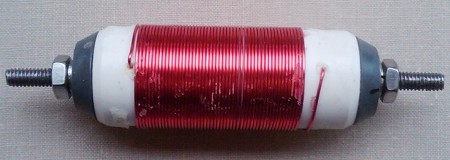
Figure 2b shows the coil without the heat-shrink cover. Measurements reveal the coil to be 51 turns of 26 AWG wire wrapped around a .85 inch form resulting in a winding length of 1.4 inches. Inductance calculators suggest this is between 20 and 30 uH.
This inductor “choke” is built clean and neat. The unique wire connection method makes for a straight wire-in/wire-out dress of the antenna wire. Nice, but what does the coil do?
The coil provides high reactance to 10m and 20m
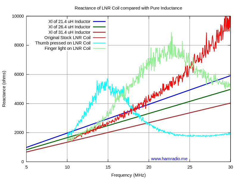
The above chart plots measured reactance of the coil from 10 MHz to 30 MHz. Calculations of Inductive reactance for three values of pure inductance are also shown as reference.
The immediate thought of many might be the inter-winding capacitance will be an issue and create trap-like behavior. Indeed we see the red trace reactance rising faster than the pure inductor and peaking somewhere above 30 MHz. Also, when I increase the capacitance by placing my thumb or fingertip on the coil, you clearly see reactance peaks at lower frequencies… just like a trap tuned for those frequencies. Standing free, however, the inductor more closely follows the reactance of a perfect inductor. Traps clearly provide lots of reactance at a narrow range of frequencies, but this one simple coil provides a modest amount of reactance over a wide range of frequencies. LNR (Par) selected this simple single coil as a compromise…, but does it work?
Choke’em
Here we see simulation current magnitudes of the LNR EF-10/20/40 antenna at 40, 20 and 10 meter operation using a perfect 26 uH inductor as choke. In this case, the antenna is oriented straight up only to highlight the currents. This doesn’t necessarily represent the best deployment in real use.
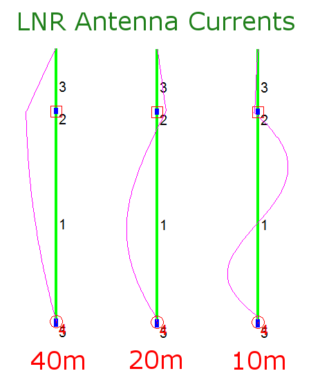
For 40m operation the choke offers the least, but not zero, reactance to the antenna currents. The coil helps resonate the antenna with its lumped inductance making it much shorter than the tradition half-wave length. The wire beyond the choke has plenty of current, but fades to nothing quick much the way documented by Terman in 1943 [1]. In this orientation we have max current near the top of the antenna.
For 20m operation the inductor chokes more, but not all, of the current leaving most of the action on the lower wire. This is a nice full length half-wave dipole antenna for 20m.
For 10m operation the inductor chokes most of the current leaving the majority on the lower wire. Here we have a full-wave antenna which will have a more figure 8 type of pattern.
It’s interesting to note when using 20m or 10m the choke is at the high impedance point of the longer wire wave form. This suggests the choking impedance needs to be higher than the 2-3 kOhms of this point. If my measurements are correct the 20m impedance of the choke equals this. This might explain the noticeable residual current above the choke. However, wire 3 is electrically short which helps keep it from being much of a player. In the 10m case, the choke impedance is higher still with the much less, but not zero residual current. This is good because wire 3 is not electrically short so the choke seems more important in this band.
For as simple as this antenna system is, it’s clear a lot of good thought went into the design resulting in a good, functional compromise of several antenna parameters. Well done.
The Impedance Match Assembly
The key to everything is the “little black box” that provides connection to a regular 50 ohm coaxial cable. I measure a direct short between the antenna terminal and the coaxial shell and center pin. This tells me this antenna uses the coaxial cable as the counterpoise as shown by AA5TB’s Figure 15.
I was so intrigued I just had to know what was inside this box…
so… I…
…cracked it open to show you in Figure 3…

Hmmm what do we have here in all that goo? I see a capacitor across the SO-239 connectors. I see a toroid wired as a transformer with a bifilar winding the first few turns… and… well, that’s it! How simple. How beautifully simple.
The schematic drawing in Figure 4 highlights the straightforward design.

There is no mystery here. T1 is a step up transformer with some compensation across the 50 ohm input. A very nice feature is the non-isolating common point to help make the coax part of the counterpoise. Indeed, this circuit looks remarkably similar to Fig. 4 in Mr. Parfitt’s expired 1980 Patent #4238799 on end feeding a “thru-the-glass” 1/2 wave mobile antenna. The notable difference is the location of the capacitor. Many EFHW designs place a capacitor on the antenna side of the transformer and tune it to resonate at one frequency. The EF-10/20/40 has no resonant “tank” circuit on the antenna side. Rather it has a 150 pF capacitance across the coaxial 50 ohm side; Measurements confirm the necessity of this capacitor in the next post.
The Big Picture View
Figure 5, below, details the entire LNR EF-10/20/40 antenna assembly and considers how it plays with the other components in a radio system.

(Click for full size PDF)
Reviews, Performance and Testing
I’ll not bore the reader with yet another performance review of this product and will, instead, invite the curious to read the many posts on E-Ham product review page which you can find here.
I’ll not consider how this antenna will perform on the air since this is so very often a subjective observation with far too many variables (Propagation, Noise, etc.) to be of much use. Let’s, instead, all agree that if we energize the end of this nice long wire of this antenna and match it well to the coaxial cable, it will perform like a traditionally fed shortened half-wave, half-wave, or full wave depending on the band. At the end of the day this is a near full size wire antenna and we all know wire antennas tend to give us decent performance.
Instead I will show extensive measurements of SWR, S11 and resistance test results of the antenna using laboratory grade equipment. Plus I will reveal any sensitivity of this antenna’s match box to nearby objects including Earth.
All this and more… in the next Test Data post.
See you next time.
73
John
References
- “Antennas,” Radio Engineers’ Handbook. Ed. Frederick E. Terman. (1st ed., pp. 795). New York and London: McGraw-Hill, 1943. Print.


 dipole antenna")
Well done sir! I tried a 40m version last night on the beach with a KX2 and was surprised at how well it worked. I prefer mono band properly tuned/resonant antennas and learned a lot from your article!! 73- Clifford KK6QMS
Hi John. I am trying to build the hwef 40,20,10 meter. Can you tell me the core that they use. It is the last part I need to get. I may have one hopefully…
John K2JHU…
Thanks for posting all this info! I just took apart my LNR Precision 10/20/40 Trail Friendly EndFed. The matchbox internals match the MKII exactly. Any idea what type of toroid is being used, maybe an FT82-43?
What impedance ratio is the match box above?
Are you sure about the gauge of wire on the choke inductor? It seems to me like it's probably 22 AWG.
51 turns of 26 AWG would be only about 0.81 inches long (smaller than the 0.85 inch diameter), but 51 turns of 22 AWG wire is about 1.29 inches long. Once you add a thin layer of enamel insulation (maybe about 0.07 inches thick total) and a tiny gap between windings, that could come out very close to the 1.4 inches long that you measured.
All of the online air core coil inductor calculators I used all agree that the inductance is around 26 to 28 uH, though.
For anyone wanting to build a clone of this antenna, I found that a 1/2" PVC pipe has almost exactly the right diameter for the choke. A 1/2" PVC pipe is 0.84" in diameter vs the 0.85" that was measured on this antenna's choke, but I doubt that tiny difference will have much effect on the inductance (you might have to add a winding to compensate, or wind it a little tighter).
Are the color codes for the pure inductors reversed? More uH should mean more XL at any frequency.