A wavelength of wire offers interesting options. Here we have one wavelength of wire fed at two different points…
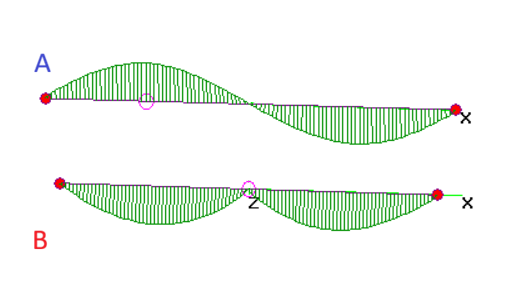
In antenna A the feed is positioned at the peak current point much like a typical center-fed dipole (half wavelength). Antenna B moves the feed to the middle of the wire. Both models were optimized in length to yield a zero reactance leaving a resistance of…
- 91 ohms for antenna A,
- 1900 ohms for antenna B.
Antenna B obviously requires a system to mate with typical feedlines. Plenty of options exist so this just a task and not a problem.
Note how Antenna B harmonized the phases so they don’t cancel. This is evident in this pattern plot of both antennas…
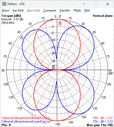
Each provides options for the radio operator. Viva la choice!