In the never ending quest to improve our HF mobile ops for the Virginia QSO Party we finally decided to try a small loop.
There is nothing new about small loop antennas. They have been discussed in the literature for decades. The ARRL has some very old articles about them in the 1968 March and July editions.
Constantine A. Balanis’ book on Antenna Theory discusses and defines large vs. small loops. This book is an essential reference if you seek the details on how loops work. The loop described below fits into the “small loop” category where the currents along the conductor are, for all practical purposes, constant. This is unlike full size antennas where current reaches a minimum where voltage approaches maximum. Since this loop is electrically short with respect to wavelength, current does not change “much.”
The bands of interest in this year’s experiments were 80 and 40 meters. We had to balance scientific research with a hard deadline of March 2010… in other words engineering.
Here are some highlights and details of our small loop…
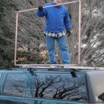
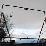
- Loop dimensions 4 – 8 feet – Fits into the bed of a full size pickup truck,
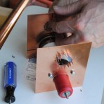
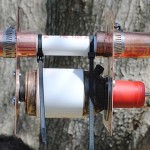
- Feed point middle of bottom horizontal conductor,
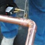
- Capacitor middle of top horizontal conductor (Note the literature describes a way to avoid having the capacitor in the top, but we stuck with the simpler approach),
- Current of loop will be tens of Amps, perhaps up to 50 A – Fat pipe necessary,
- Voltage across Capacitor will be thousands of volts, perhaps up to 5 kV – Vacuum Variable is an good choice,
- We used shunt loop feed at bottom,
- We used 1 inch plumbing pipe and elbows,
- Silver solder a must to keep conductivity high,
- Vacuum variable capacitor selected to provide tuning capability – some use coaxial cable caps for fixed frequency use.
Here are various pictures…


Did it work?
It sure did. You might notice we never finished a method to tune the vacuum variable remotely so we were stuck with leaving the thing tuned for 7265 kHz. However, the mobile operator made frequent AB comparisons between the loop and his 40 meter ham stick. I was on the other end of the contact several times and could not tell any difference. This does not suggest the loop was better than the ham stick, but at least the loop didn’t stink.
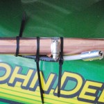
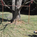
We were pressed for time to get this thing on the air for VAQP 2010 so the mobile operator took the loop as is from our tree testing. During the contest he found the feed loop worked with a much smaller diameter than we originally anticipated. On the fly adjustments resulted in this final configuration here…

There are several things left to do including engineering some way to tune the vacuum variable remotely. This will be well worth the effort since our manual tuning revealed this should work on a variety of bands. The capacitor is a surplus 5-500 pF (5 to 3 kV) model form Surplus Sales.
According to the literature, small “magnetic” loops like this have an antenna aperture similar to a full size dipole. If this is true it should be an impressive benefit for otherwise compromised mobile operations.
If you are considering a small loop antenna be sure to understand this is a very small bandwidth antenna. A future post will provide details, but don’t expect the bandwidth to exceed a few kHz from center. You cannot use a traditional tuner with this antenna. The variable capacitor is the only way to move the frequency.
As a first foray into Magnetic Loop antennas, I think we achieved success. Work still needs to be done to see if this really is a practical antenna for mobile (or even fixed) use, but results show promise.
Thanks go out to W2BRI’s web site for lots of great ideas…


