More than a few Zed Threads touch on the subject of magnetic mount antennas for VHF/UHF mobile use. Some suggest there is a penalty to pay using a magmount base both mechanically and electrically. The mechanical issues are relatively obvious to most everyone. Folks can make their own choice based on mere observation and critique. The electrical penalty is a bit more obscure for most. I’ve written one article previously on this topic…
Let’s pull in the primary graphic from the above…
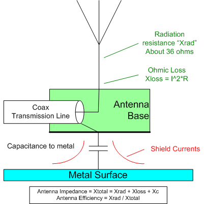
The primary, and perfectly reasonable, question posed by the anti-mag folks is how the capacitive reactance in series to ground affects performance. I finally found some time to perform some actual gain measurements along with the obligatory reflection measurements.
Measurement setup
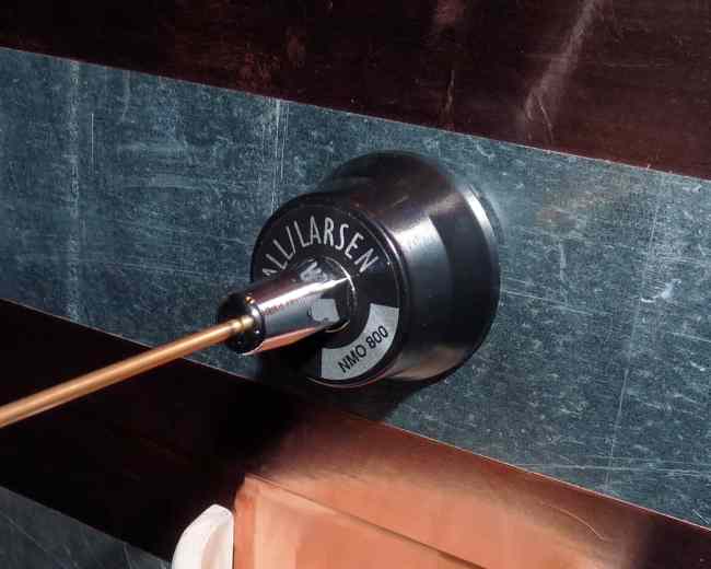
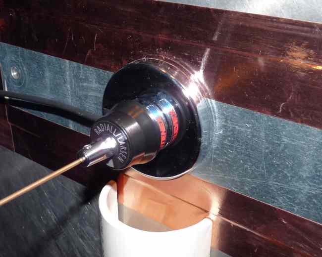
We have an enormous four foot diameter aluminum circle perfect for VHF monopole measurements. Since we are also testing magnetic mount antennas, a piece of ferrous metal is attached at the mount point. There are two mount options for this test: NMO thru-hole mount and NMO magnetic base. For the directly connected NMO mount, I used the 3/8″ thru-hole model from previous tests. The back end of this mount has twelve feet of RG-58 coax. For the magnetic mount I used the model shown below also with 12 feet of RG-58 coax. The antenna under test is a copper 1/4 wave monopole tuned to about 151 MHz on the direct mount. Thus cut, this monopole remained the same length for all tests.
Figures 2a and 2b
Return loss measurements of 1/4 wave monopole on 4 foot ground plane
This test merely repeats the magmount reflection measurements made by thousands of amateur radio operators. We all know magmount antennas look good on the VSWR meter and this test is no exception.
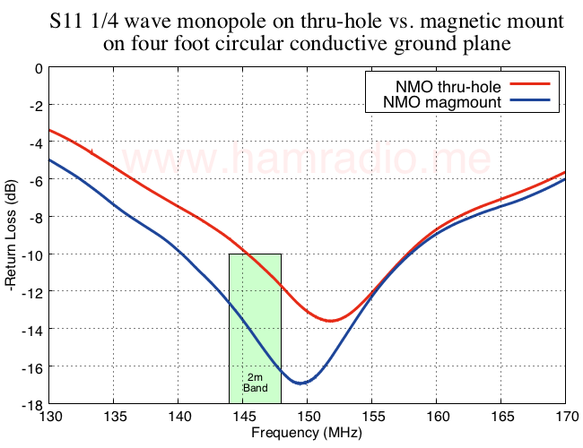
The chamber’s lowest frequency is 150 MHz. Hence the antenna under test was tuned close to this frequency. I show the 2m band for reference only. The difference between the two mount options is certainly noticeable, but not really news given the many previous measurements made by others. The return loss for the directly connected monopole shows what you might expect of an antenna at around 30 ohms impedance. The magmount’s capacitor may add just enough impedance to approach 50 ohms and give the deeper return loss.
S11 and VSWR measurements are important, but don’t tell the story of how the antenna performs in pattern and gain. For that we need to spin the antenna and 4 foot ground plane in the E-Plane and measure the gain.
E-Plane gain measurements of 1/4 wave monopole on 4 foot ground plane
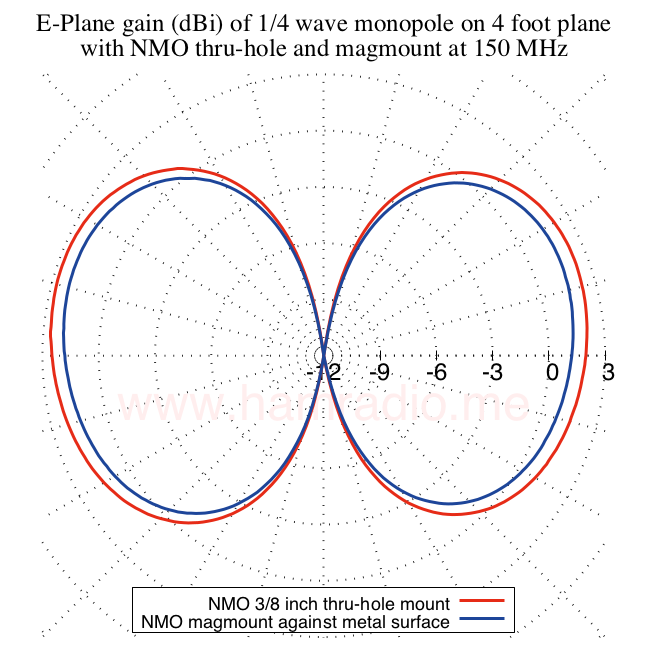
Here we see the E-Plane cut at 150 MHz of the directly mounted NMO vs. the magnetic option.
A bit of a difference, but when we place a thin piece of insulating material between the magmount and the ground plane to represent paint and finish we get this…
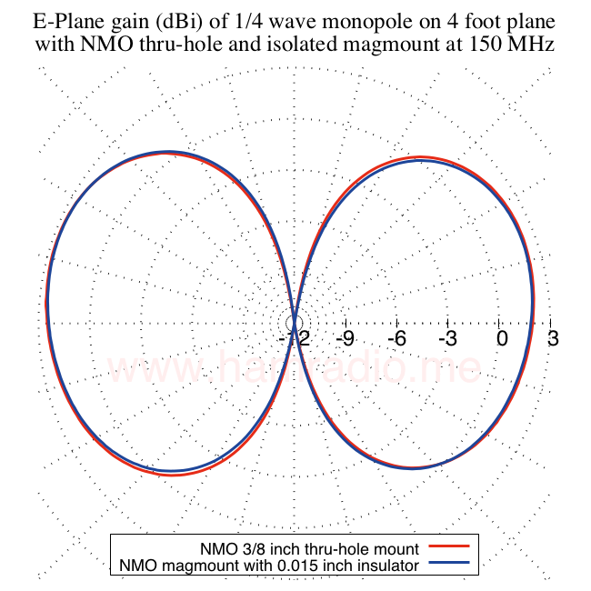
The results are from a calibrated measurement chamber and include the approximate 1 dB loss from the 12 feet of RG-58. The 15 dB radial axis range helps reveal subtle differences between the two measurements.
Conclusions from these measurements
For all practical purposes the performance of both options are identical. The relatively low reactive impedance presented by the magmount in series with the relatively high 30+ ohm radiation resistance = NBD.
I should note I did measure the dc resistance between the magmount shield and the ground plane when mounted without the insulator. I found a somewhat unsettling value of a couple hundred ohms. You would think it would be a reasonable connection or wide open… not something sort of in between. Hence I wondered if this partial connectivity could make a “dc” connection between coax shield and ground plane to produce these results. Adding the insulating dielectric seems to preserve the performance and even enhance the magmount’s gain.
Let’s vary the insulator thickness and see what happens.
Adding insulating dielectric between magmount base and ground plane
I found a variety of insulating materials around the shop to separate the magnetic base from the ground plane and provide a variety of thicknesses between the two.
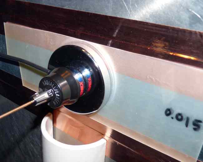
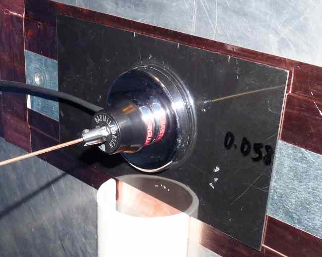
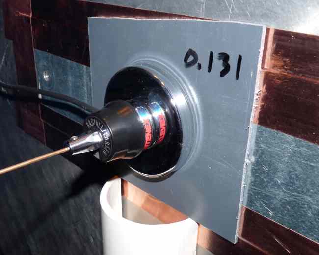
Figures 6a, 6b and 6c.
Do these configurations spoil the antenna performance? Let’s see S11 first.
Return loss measurements of 1/4 wave monopole with insulators
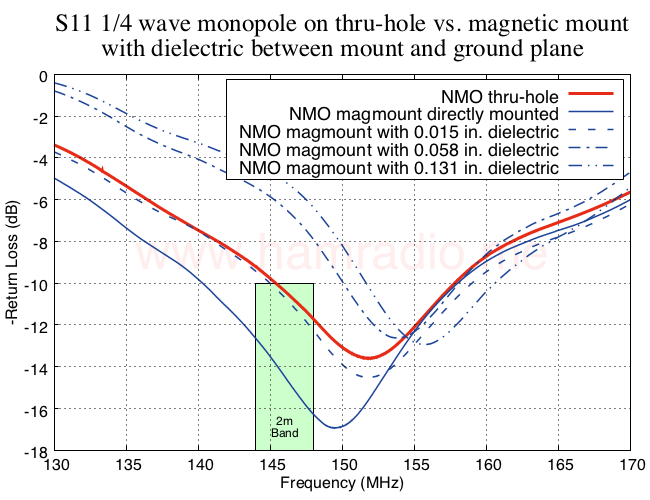
Return loss provides a sensitive view of the changes in the reflection coefficient. We see an interesting trend as the thickness increases. The 0.131 thickness weakens the magnetic “grip” and represents the point of impracticality… much like ludicrous speed in Space Balls. Still it’s nice to know we achieve mechanical failure well before electrical compromise… or so it seems.
E-plane gain of 1/4 wave monopole with varying insulators between magmount and ground plane
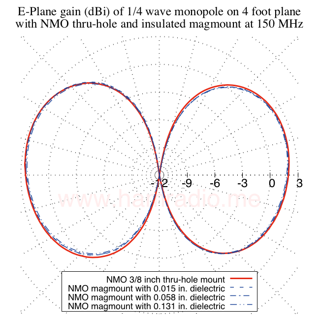
Actual antenna gain and antenna pattern are where the rubber meets the road in antenna performance and the above plot shows no practical difference in every tested gap between the magmount and ground. With the iffy dc connection removed from the picture, it’s quite obvious the capacitive coupling provided by the magmount base is plenty sufficient to “ground” the shield currents quite effectively.
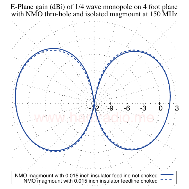
When does the coax become the counterpoise?
At some point the capacitive connection to ground plane puts more reliance on the feedline shield to provide the “other half” of the “Marconi” antenna configuration. Fortunately the feedline is very easy to isolate with ferrite chokes at 150 MHz. The following figure compares the E-Plane gain of the practical thin insulated magmount with and without feedline chokes. In the choked case, two type 44 clamp ons were placed on the feedline as close to the mount as possible. Additionally, a third type 44 was placed a 1/4 wave away. CHOKED!
Conclusions
The chamber measurements confirm what many observe… magnetic mount antennas do provide at least “some connection” between shield currents and the ground without fuss. In addition, we did notice a frequency dependent worsening as frequency lowers (capacitance reactance increases), but, again, this is already well known in the various ham watering holes. Hence, maximizing the capacitance is always a good goal and especially important for 6m and lower. These longer antennas require a more stout mechanical support anyway.
There are lots of mechanical reasons to avoid magnetic mount antennas including the harm they do to automotive finishes. The above test confirms they work electrically on par with the shield-direct-connect options such as thru-hole NMO mounts.
If you must use a magnetic mount antenna and have concerns over your paint finish, consider the various pads available to place between antenna and vehicle. The above tests show quite clearly you are unlikely to spoil antenna performance due to the pad’s extra separation.
Previously, I’ve never seen an actual antenna pattern and gain comparison between non-mag and mag antennas. I hope these results prove helpful to the debate. Interpret as you wish.
Great write-up. Really helped to clear some things up for me. Thank you!
Nicely done. Thanks!
Magmount antennas for 2m and 70cm are often underappreciated. Stick a good mag mount in the middle of a metal car roof and it will perform well.
Bob K0NR
Mag Mounts can work for you…
I work for a company in the two-way Radio & accessory manufacturing area.
At work we did some pre-tuning for a customer of a batch of MidBand VHF antennas on MagMounts earlier this week.
Often when you see a 1/4 wave on a mount the SWR isn't that low as its not a 50ohm match
(pretend I'm not advertising)
Our Mag mount feeds the whip a ways off the plane & is closer to 50ohm than when a mount is directly on the plane.
Certainly makes the matching better, = wider 2:1 BW etc, i.e. the curve is lower (closer to 50ohm) so BW is wider at 2:1
SWR 1:1 (at end of 5m RG58 cable, 80MHz)
Dom (VK2JNA)
Great write up! Thank you! Can you do a comparison with a glass mounted antenna like the tram 1191?
Great objective analysis. Much appreciated.
How do you think that the results will be similar when a 1/2 wave whip is substituted for the 1/4 – all else being the same?
It seems to me the capacitive coupling principal is the same, but the current and voltage nodes are likely to be different. How would this effect the results with a 1/2 wave element?
I think an EFHW atop a mag mount should work well.
Great write up John! Thanks for posting and sharing the results. For installers, would be interested in seeing results e.g E plane gain in comparison to placement of magmounts on the vic. As well as up armoured vs thin skinned impacting capicitance perhaps??
Would the cabe used impact the counterpoise? LMR-240, RG-58, LMR-195 etc?