Last month I had a nice PSK31 dialog with W1NDY. He described a desire to raise and lower his tower remotely as it currently involves the use of two people, he and his XYL, to perform the operation outside in the elements.
A long time ago in a land far far away I was working with the Navy Prototype Optical Interferometer Telescope in Flagstaff, AZ. One of the requirements was to raise and lower an assembly of mirrors up and down. The only positions of this “elevator” were top and bottom; No middle “floors” were needed in this application.
After some research I stumbled into the circuit animated below in Figure 1. Essentially, if your elevator motor is a DC motor, you can use two limit switches, S2 and S3, to affect a “hit the limit” system which will properly stop and wait till you reverse the voltage. Switching S1 to “up” is all you have to do. When done operating, switch S1 to “down” and the system will lower and stop automatically.
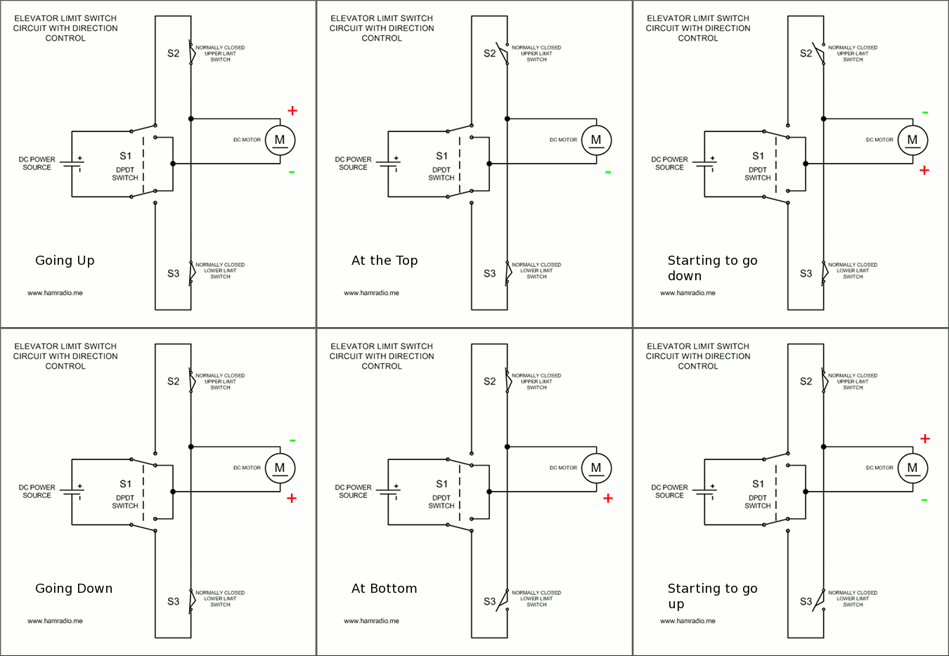
Switch S1 could also be an H-Bridge circuit that applies positive or reverse polarity to the system. This is handy if you desire logic control of your tower raising. However, for this example, a simple manual DPDT switch provides a simple flip and wait system.
The following features and requirements of this system include:
- Locate switch S2 where it will “open” once the tower reaches the desired height.
- Locate switch S3 where it will “open” once the tower reaches the desired retraction height.
- The DC Motor is wired such that it raises the tower with positive polarity and vice versa. This precludes the use of AC motors… at least directly.
- All switches, S1-3, must handle full motor current and at least double the system voltage to properly handle the inductive voltage spikes caused by opening contacts.
- Make sure all wiring is suitably sized to handle the full motor current without too much voltage drop and/or excessive wire heating.
Let’s review each step of operation starting with the tower fully retracted.
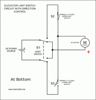
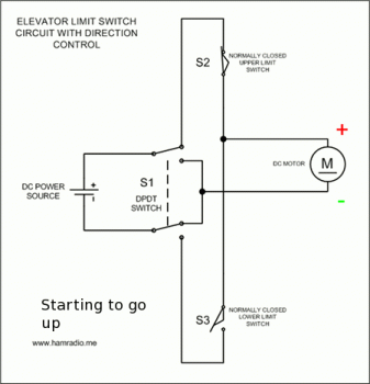
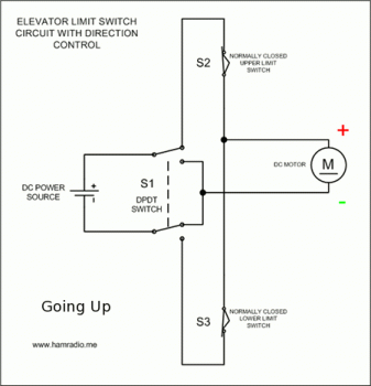
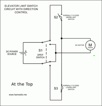
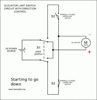
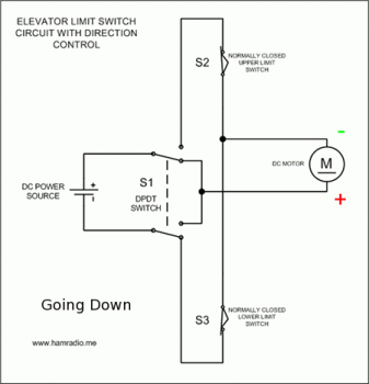
After the elevator finishes descending, we are back at the state in Figure 2.
For many of you this whole concept will not apply since you have AC motors on your tower raising system. W1NDY apparently has a DC system and I have seen a few aluminum tower demonstrations online that show a simple hand held drill raising and lowering the tower. Here is one…
Video Removed
So, apparently, the DC motor approach is a reality for some systems.
One particularly important point of a system like this is to ensure the limit switches, S2 and S3, are normally closed. Additionally, your limit detection mechanical assembly must not overrun. What I mean by this is as soon as you hit the limit and either switch opens, make sure the tower does not overshoot and cause the switch to close again… beyond the limit! That would overrun the tower and not be good. Make sure your switches open and stay that way for the entire time it takes for the tower to slow down to zero velocity.
The above circuit is remarkably simple. It has been around the Internet for decades and is nothing new. I hope it helps someone.
73
John

your the best info iv seen in the like 4 days of researching lol thank you great work