Bettering the Dipole Antenna
The 80m Amateur Radio band is wide… very wide. Covering 3500 to 4000 kHz, this band extends well beyond the normal resonant range of a single dipole antenna.
Short of simply pressing “TUNE” on my rig’s internal antenna tuning system and living with the high SWRs, I really wanted to try something a bit more… shall I say… clever.
Sure enough, many approaches, both old and new, exist to help an 80 or 75m dipole present a decent SWR across the entire 80m band. Many excellent examples are highlighted in Chapter 9 of the 21st Edition of the ARRL Antenna Book[1].
80m Wideband Dipole Antenna Requirements
Given time, many approaches in the Antenna Book would be well worth a try. However, time is something I did not have since I decided to explore this topic the Monday before the weekend Virginia QSO Party event. My total list of requirements included:
- Optimize antenna for use in a particular Amateur Radio Contest called the Virginia QSO Party.
- Modify existing 80m dipole to cover entire 500 kHz width of the band.
- Ensure it works in the Inverted V configuration.
- It’s Monday (March 11) and this needs to be done by Friday (March 15).
- Keep costs below $100.
- Dipole in Near Vertical Incidence Skywave (NVIS) configuration (aka Cloud Burner) – Best supports in state communication.
Contending 80m Wideband Dipole Antenna Approaches
Here are the possibilities I came up with:
- Do absolutely nothing and tune the actual dipole for a specific portion of the band.
- Matching network at radio – Internal Tuner
- Transmission Line Resonator – Series
- Fatter “Cage” dipole
- Double Bazooka
- Crossed Double Bazooka
- Matching network at feed point
- Transmission Line Resonator – Stubs
Doing nothing is no fun so Approach #1 is out. Using the internal radio tuner is certainly workable, but not elegant. Scratch approach #2.
I thought real hard about the naturally wide band Cage Dipole. I even ran quite a few simulations (see below), but quickly figured it would take too much time and materials. Scratch 4.
The requirement to use my existing dipole (Req. #2) instantly ruled out all the interesting approaches in the Antenna Book involving a redo of my current dipole cut for ~3.8 MHz. These designs are inviting though. Much of Antenna Book content comes from Frank Witt’s 1986 QST Article highlighting several coaxial resonator solutions[2]. Especially noteworthy is Witt’s discussion of antenna system efficiency as an important consideration beyond mere SWR. Antenna element resonators deserve a good hard look, but only when I have more than four days. Scratch 5 and 6.
I looked at a fixed matching network at the antenna feed point with interest. Note this is not an active tuner that adjusts for the particular frequency at that moment, but an arrangement of components that, once set, stay set, and present lower SWR across the 80m/75m band. Hmmm, well I would have liked to try this, but component availability was a big question in the short time frame. Scratch #7… for now.
This leaves approaches #3 and #8: Transmission Line Resonator (TLR) Series and Stubs. Both TLR approaches use a a basic dipole cut to the midpoint of the band of interest. As I already have a dipole cut to 3.8 MHz, these promised quick build times. I have whittled the choices down to these two.
Transmission Line Resonator – Series or Stubs
Of these two approaches the one with stubs provides a feedline solution much shorter than the series resonator system. In this particular instance, I had over 300 feet between antenna and station so the shorter approach didn’t matter.
One advantage of the Stub TLR approach is it uses 50 ohm coax for all transmission line components. Contrast this with the Series TLR which has a length of 75 ohm coax. I did not have 75 ohm coax on hand and needed to see how easy and quick I could obtain some. Note I could easily buy RG6 locally, but I was hoping for RG11 so I could use typical ham coax connectors.
DX Engineering is able to ship within a day to my QTH. A quick check of their web site confirms RG11 is available at a reasonable price. After a few more Monday afternoon minutes pondering all the above, I placed an order for about 60 feet of RG11 (enough for a 1/4 wavelength at 3.75 MHz) and a couple of the dreaded UHF solder connectors.
Once I received confirmation of my order, I put all the above to rest and settled on making the TLR Series feedline to broaden the bandwidth of my 80m dipole.
Transmission Line Resonator
With that in mind here is the diagram of this approach.

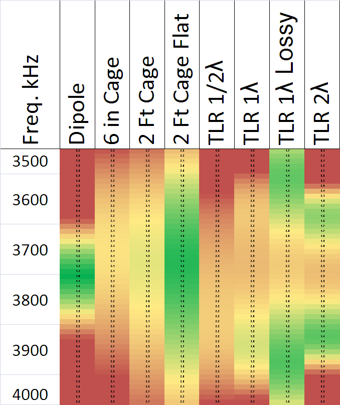
The Antenna Book suggests the resonator must be a multiple of 1/2 wavelengths at the frequency of the dipole antenna. EZNEC (and I guess any NEC) provides the ability to simulate transmission lines along with the antenna elements. I used this to examine and compare the SWR plots of 1/2, 1 and 2 wavelength resonators. I also simulated the Cage dipole in a few configurations. A plot of all these SWR curves is usually the right thing to create, but I found the heat-map function in Excel to be more visually interesting. In the figure below, green shows an SWR of 1:1, yellow 2:1 and red 3:1 or more. With the exception of the 2 Foot Cage dipole in the flat configuration, all the simulations have the dipole in Inverted V with the apex at 48 feet AGL and ends about 9 feet AGL. All this is above average ground (.005/13).
Simple Dipole
In the first data column you see the problem with a simple dipole we are trying to solve; It’s just too narrow a bandwidth to cover much of the 80m band without some sort of intervention. The good news for CW fans is simply cutting the dipole a bit longer will give you full coverage from 3500 to 3600 kHz. If this is all you care about, you’re done.
Cage Dipoles – Natural Wideband Antennas
The best and flattest SWR comes from the 2 foot diameter Cage dipole in the flat top configuration. Despite the large amount of wire one needs for this, I have to admit an antenna that is naturally wideband is very appealing. Even with the 2 foot cage in the Inverted V shape, the SWR is very flat, but a bit higher overall.
Transmission Line Resonator Solutions
Moving on to the TLR Series simulations we see how changing the length of the 50 ohm portion seems to change the overall bandwidth of the resulting SWR. The 1/2 wave resonator provides some broadening, but not really enough to be thought a solution. The 1 wave resonator begins to show how the SWR minimums split into two frequencies. The far right column shows the effect of 2 wave resonator with two well defined minimums, but still not quite covering the entire band.
Finally, I added some real cable loss (LMR-240UF) into the simulation and found the 1 wave resonator amply covers the entire 80m band with decent SWR. Great!
Disconcerting is the sensitivity of the resulting SWR curve to environment variables including cable loss. At this point, though, I have enough confidence to move ahead with construction.
Build the 80m dipole Transmission Line Resonator
The 80m dipole was already on its 48 foot mast with a DX Engineering balun and original coax. All I needed to fabricate is a replacement 50 ohm coax 1 wave in length and a 1/4 wave length of 75 ohm coax. I had LMR-240 Ultraflex on hand for the 50 ohm piece. DX Engineering promptly shipped my piece of RG11 along with some solder type UHF connectors.
I used a Network Analyzer to absolutely nail the electrical length of each piece to well within 1 phase degree of my target lengths based on 3.75 MHz. Yes I realize my current dipole resonates at 3.8 MHz, but eventually I will lengthen it a bit. After cutting the coax pieces, I simply connected them together and set off to the antenna’s location for installation and measurement.
Measurements of 80m Dipole with Transmission Line Resonator
I used a network analyzer to measure the before and after effects replacing only the feed system with the TLR Series system. Three curves are shown:
- The SWR measurement of the 80m dipole with 250 feet of 50 ohm coax (Black),
- The SWR simulation of the 80m dipole with “lossy” transmission line resonator and 75 ohm Q section (Red),
- The SWR measurement of the 80m dipole with “actual” transmission line resonator and 75 ohm Q section (Green).
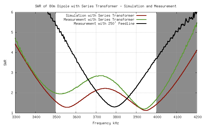
The green trace attests to the success of broadening the bandwidth of my existing dipole. As this was the day before the Virginia QSO Party, this was good enough and so we went with it. The antenna performed well during the weekend and required modest tuning when switching modes.
The slight “tilt” of the TLR measurement was confusing, but I brushed it off as an artifact of my dipole being resonant above the 3.75 MHz design lengths.
Lessons Learned
After the contest, I thought more about why the TLR measurement was not in agreement with simulation. I ran various modifications through simulation looking for a matching SWR curve. I found it by lengthening the 1 wavelength section a few feet resulting in this plot.
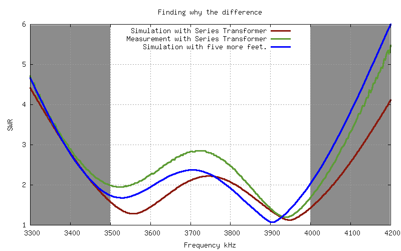
The blue trace shows the simulation trend of adding five feet to the 1 wavelength section. It’s not an exact match, but, given the many variables of the system, suggests I did somehow cut the 50 ohm section too long.
How?
I was very careful with my measurements using an actual network analyzer to measure the electrical length… thus avoiding the potential errors of calculating with published velocity factors. Hmmm… what could I have… oh wait…
In my haste to finish this project before the weekend I made the incorrect assumption the dipole feed point is the connector on the Balun and not the antenna element terminals. The Balun is part of the TLR length and it most likely has a length of coax wrapped around or through some toroids! Oops.
When I get a chance I will shorten the 50 ohm resonator to compensate for the DX Engineering balun. Rather than guess what the electrical “length” of the balun is, I will simply include it during phase measurement with the network analyzer.
Conclusions
Despite my error omitting the Balun length from the resonator length, the above series Transmission Line Resonator shows great promise in making a simple dipole cut for the middle of the 80m band present a decent, but certainly not perfect, SWR across the entire band. It is just one of several possible techniques. Given my particular need for a quick turnaround, the series TLR was the right choice.
Some points to keep in mind include:
- The Series TLR significantly improves the bandwidth of a simple dipole, but it does not achieve 1:1 across the whole band. You may still need some antenna tuning at the radio end to avoid power roll-back.
- If you use your radio or shack tuner, it will have an easier time at the band edges while using the TLR with your dipole.
- Despite the tolerable SWR the TLR presents to your shack, the resonator and Q sections of coax will have some standing waves present with accompanying losses. There is no free lunch using the TLR.
- I used LMR-240 Ultraflex because that’s what I had available. Larger coax makes sense for permanent installations and will reduce standing wave losses. However, recall from the data above, coax losses change the behavior of the TLR a bit. The phrase “Your Mileage May Vary” applies very well here.
The technique above works with some limitations. It may well be worth a try for many. Please read Chapter 9 of the ARRL Antenna Book (21st Edition) to learn more.
References
- Straw, R. Dean. Ed. ARRL Antenna Book. 21st Edition. American Radio Relay League. Newington, CT. 2007. Print.
- Witt, Frank J. (October 1986). “Broadband Dipoles – Some New Insights”. QST Magazine: 27-37.


Hi, I am worrying about the 100m coax cable inserted…huh? It can be a lot of insertion loss, isn't it?
John said he has a 300ft run to the antenna, so he did not add any length. Best I can tell he just replaced a quarter wave length worth with 75ohm cable. Does that help?
Be careful of retun loss! A lot of coax doesn't radiate anything. SWR is not the "end all". To illustrate, one can use a large roll of RG-58 with the opposite end shorted from center conductor to shield as a great dummy load at 900MHz and above. The forward and return losses are so high that the ratio of forward power reflected to power input makes the SWR look like a great antenna match.