Coaxial Dipole Driver for Yagi-Uda Antennas
Antenna geeks rejoice… you have another great antenna web site to visit during your next armchair browsing session.
I came across the website of Derek Hilleard, G4CQM, containing a wonderful assortment of details to help make your next Yagi-Uda project antenna a success.
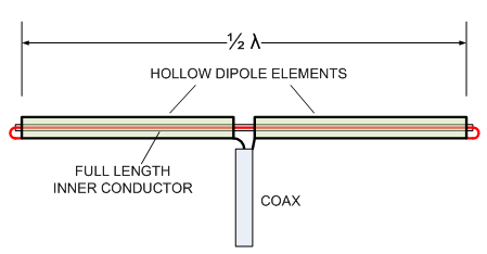
I’m always on the prowl for innovative, and functional, ways of feeding Yagi-Uda antennas with 50 ohm cable. Derek explains the Coaxial Dipole as a way to obtain 50 ohm, and perhaps a self-balancing, feed for Yagi-Uda antenna designs using two hollow tubes containing a wire within.
It’s worth noting this topology doesn’t miraculously turn any parasitic antenna into a 50 ohm system without due diligence and design of the entire antenna system. In fact it’s not quite clear what the natural impedance of this thing is. The more important claim is the full wave path that provides, at resonance, a self-balancing feature.
Also note the axiom “Coaxial Dipole” describes more than this concept such as the vertical coaxial dipole shown in this J-Pole vs. Coaxial Dipole article.
Here’s the site…
Details include:
- It’s a loop partly contained within a tube.
- The folded branch (inside the tube) does not radiate resulting in increasing the bandwidth, like other folded dipoles, but without affecting the input impedance.[1]
- Allegedly performs the same self-balancing behavior like any full wave loop as discussed in the Loop Fed Array (LFA) article. NOTE: Simulations (non NEC) suggest this is not the case… see below.
- Free to use for anyone as a 1963 paper describes the technique.[1]
Preliminary Findings
Without a doubt, this innovative technique begs for some simulation and lab verification. The details on his web site are food for thought for now, but stimulus for experimentation. I’ve added this to my list and will share results soonest.
A quick run of modeling the various configurations in an FDTD simulation provides the following data.
| Test # | Description | 1/4 Wave Feedline |
Feedline Current |
Result |
|---|---|---|---|---|
| 1 | Cylindrical Dipole | None | n/a | Classic Dipole Pattern |
| 2 | Cylindrical Dipole | Yes | High Current | Tilted Pattern |
| 3 | Folded Cylindrical Dipole | Yes | Low Current | Almost the same as test #1 |
| 4 | Coaxial Dipole | Yes | High Current | Tilted Pattern |
This simulation suggests:
- The Folded Dipole exhibits the self-balancing behavior. The feed impedance is several times higher than the cylindrical dipole’s.
- The Coaxial Dipole lacks the self-balancing behavior. The feed impedance is similar to the cylindrical dipole.
Both being full wave loops, this difference in behavior of the Folded vs. Coaxial dipole is a surprise.
Lab testing is the logical next step before we proclaim a verdict.
References
- Page, H. (1963). An Introduction to the Theory of Aerials. (p 69 – pdfpage 77). British Broadcasting Corporation Engineering Division.


Hi Having built a number of G4CQM`s antennas over the years they all work well.
on 2 and 70cms even using wooden booms for proof of concept before committing ally boom money! on 70cms with an old 14ele design worked into Germany with 20w ft897 firing into a bank of tree`s 15`agl and Spain again using ft897 on 2mtrs on same mast .
Regards Jon G8CCL.
Ever do any lab testing? in field testing?
None yet. Way too busy.
Ive built a number of Derek's designs from 2m to 23cm and all work very well.
Im not sure about the "Tilted Pattern" referred to above as Ive seen no evidence of that used as a driven element in a Yagi, not surprising really.
I do decouple the coax with the raised loop as the coax leaves the dipole and on 23cm Ive found that taking the coax down through the boom directly from the dipole also helps in a better match.
Good simple dipole that can be used on any 50ohm ant.
Roger ZL3RC
Just realized that this is an older thread, but since antenna theory is timeless I've choosen to share my viewpoints.
Without the inner conductor the hollow dipole will act as an open ended transmission line.
My guess is that you will need to match the impedance of the wire "thru the dipole" close to this or mayby not at all.
Problem: High impendance "coax" => Low Cut-off Frequency!
Solution: Reflections due to mismatch may be irrelevant if the setup is pefectly balanced. ( Well in theory at least. )
Lets see it another way.
Theory dictates that the current in the end of a 1/2 wave dipole should be 0.
If the inner conductor is matched and doesn't emit anything it will remain 0.
This means that : Impedance at endpoint = Infinity.
There's no I-components either real or complex!
Apart from the "bandwidth limiting feature" it doesn't matter if the inner conductor is there or not!
Maybe it's better balanced – who knows? – Electrically It's still a 1/2 wave dipole!