Hammy eyes
Has the ever happened to you?
Imagine driving through the countryside with the XYL where she admires the bucolic farmland passing by…

Alas your XYL is the long suffering wife of an amateur radio operator with hammy vision superpowers…
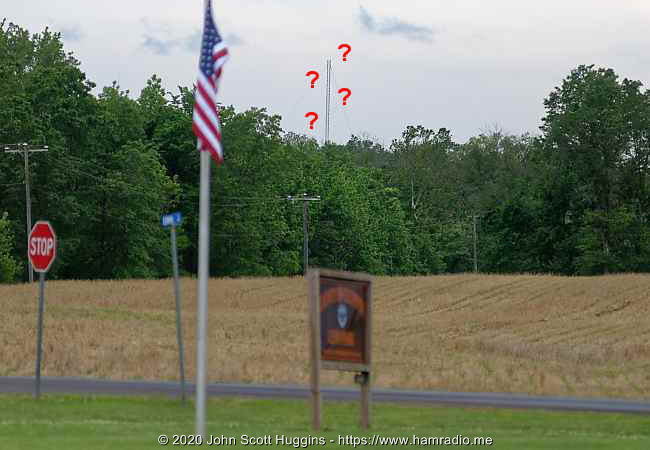
“Hmm, what is this” you mumble. You turn right onto a gravel road leading to a vineyard, but by sheer coincidence you pass by your real quarry…
“Okay honey, I will be just a few minutes having a good look at this thing” you say with clenched teeth. You grab your camera with long lens and proceed to study of one of the few remaining LF beacons still in use for aviation.
Culpeper Non Directional Beacon (NDB)

This navigation aid is five miles south-south-west of Culpeper Regional Airport providing a runway center line fix for inbound aircraft. Airnav.com confirms this beacon is still in use and provides details…
- Frequency: 351 kHz
- Morse ID: MSQ
- Power: 25 watts
Authorities have been decommissioning these beacons aplenty, but this one still is heard where I live 13 miles north. The car’s AM radio confirms some desense so it clearly has energy in its near-field.
There use to be a beacon on the airport premises, but that is long gone as are a great many others in Virginia. For whatever reason, MSQ still exists.
Medium Frequency Beacon
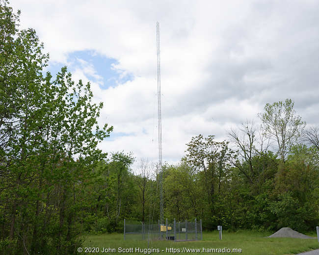
In the US, airway beacons operate between 190 and 535 kHz so technically straddle the 1000 meter wavelength line between LF and MF bands. Such long wavelengths present an economic and engineering challenge to the transmitting station designer and builder. An eyeball survey suggests the tower height at this station is about 90 feet (~27 m) based on nine sections of tower. With this in mind, the design challenge becomes familiar to mobile amateur operators attempting 80 and 40m on their vehicles, but at a much larger scale.
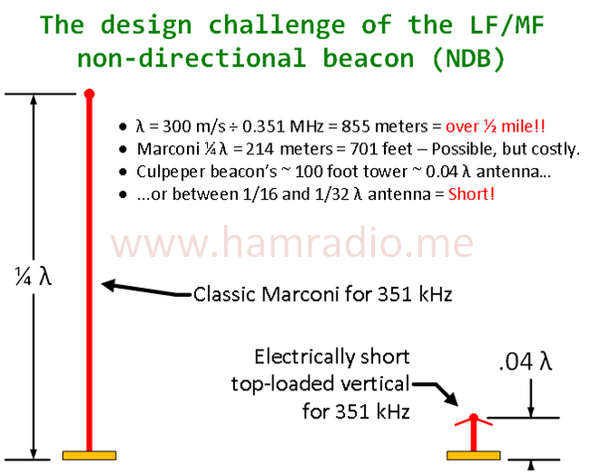
Compared to the exemplar Marconi 1/4 wave monopole, the NDB station antenna is minute. As the above height comparison reveals, the beacon facility has a very electrically-short radiator. At 351 kHz frequency, we’re dealing with a wavelength of over a half mile (.85 km) so any small antenna system that is going to radiate this 25 watts effectively deserves a study.
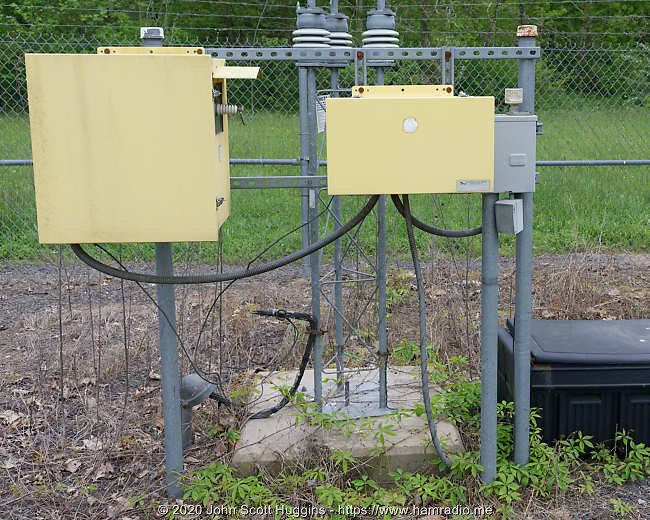
Starting at the bottom
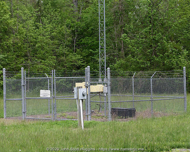
Other than the guy wire footings, everything is nicely contained within the small fence. This is for security to be sure, but, as we shall see below, safety as well.
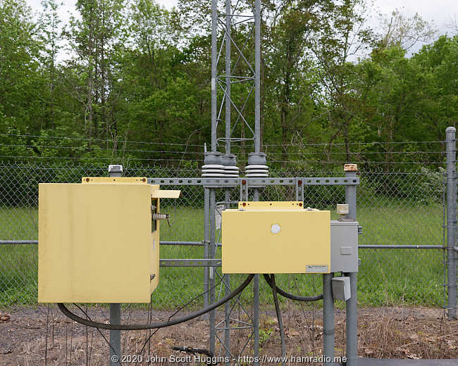
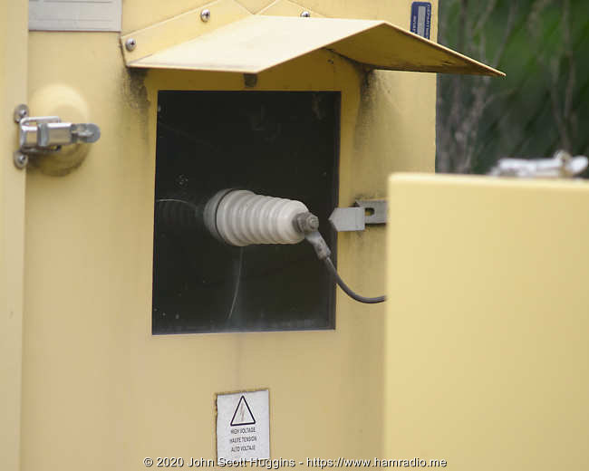
My guess is the transmitter gear is housed in the right yellow box next to the ac power feed. The large diameter conduit connects the transmitter to the left yellow box I assume is nothing more than a passive antenna matching system.
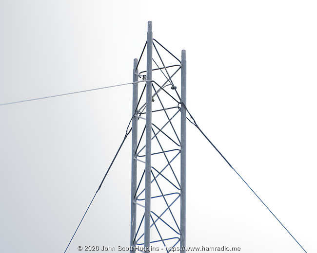
The tower appears to be of simple galvanized steel construction with impressive insulator supports.
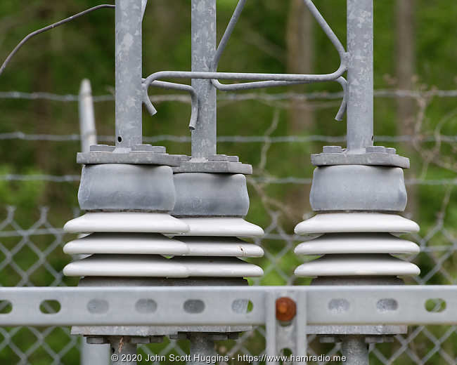
How about a closer look.
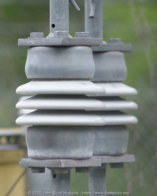
The feedpoint
Have a look at… THIS!!!
Many of you are probably thinking “All this? For just 25 watts!?!” Indeed an electrically short antenna requires a bit of Smith chart extremes in the matching department that involve high voltages as we will see in the analysis below. Hams being hams, we focus on details like terminals so let’s do just that.
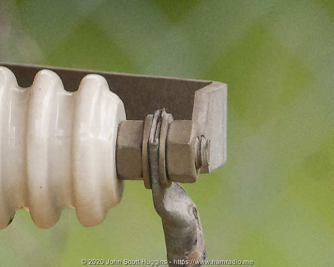
She’s a beaut. The copper wire gently bends up to the tower connection point where it simply clamps onto the galvanized lattice.
And that’s it! Not really all that extravagant.
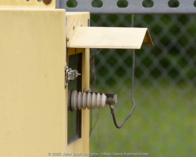
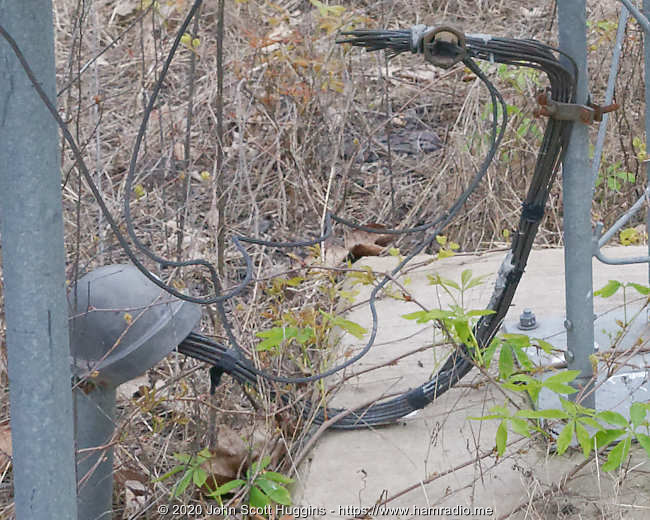
Hmmm, what about lightning, surge, etc.
The tower is electrically isolated from ground and energized by the copper wire from the yellow box. Assuming the guying system does not ground the tower, we should wonder how electrical charge buildup or lightning events find a way to earth. If you were paying attention to the photos above of the insulator terminal, you see a piece of metal behind it. Here are better views…
The pointy terminal air gap is apparent in the above photo.
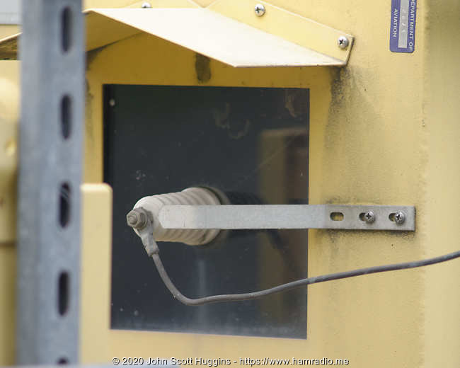
A thick strap attached with just a couple of screws to the case provides the path to ground.
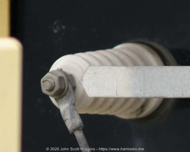
The gap is pretty large at around an inch or so. I assume some sort of static drain is built into the transmitter/matching system leaving this gap to provide last effort shunting only for, I assume, lightning events. This is just a guess, but I think a reasonable one.
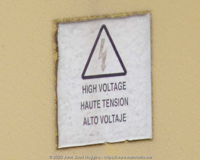
No kidding… I have little doubt this sign is to be taken seriously.
Going up the tower – insulated guy wires
This tower has three sets of guy wires. The bottom and middle set look like this.
It’s hard to tell in the photo, but the galvanized wire loop around the tower legs ends in a bolt shared with what appears to be non-conductive line. Here’s a close up of the guy on the right.
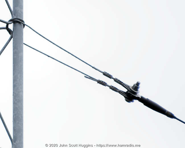
The attachment guys are marginally connected electrically, being just wrapped a bit around the tower leg. However, the remaining length past the bolt appears non conductive. Breaking up or otherwise ensuring guy wires do not interfere with the operation of an active vertical radiator makes perfect sense.
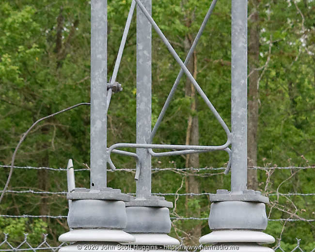
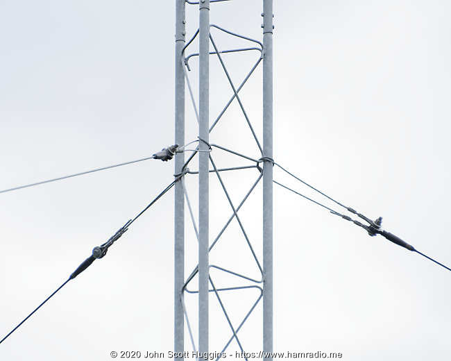
Top of the tower – non-insulated guy wires
At the top of the tower we find something completely different.
We see the same galvanized wire wrapping around the tower posts, but there are some extra wires involved. Let’s have a closer look…
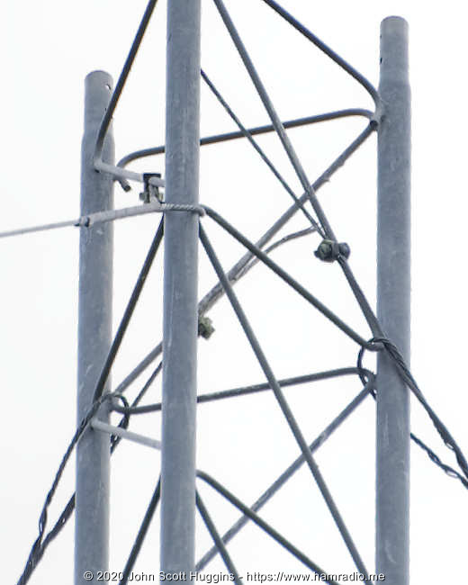
It’s a bit difficult to see, but an extra pigtail of galvanized wire is spliced into the main guy and then clamped securely to the tower lattice. It’s clear the designer meant for these guy wires to have a secure electrical connection to the top of the tower while simultaneously providing mechanical support.
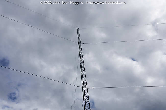
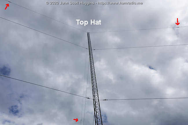
Antenna top hat
Here’s a view up the tower showing all three sets of guys.
We see the lower and middle guy wires with a darker guy material plus those transition clamps close to the tower. The electrically connected galvanized top guy wires go out a bit and appear to terminate at transition points at the red arrows (below). Assuming these transition points insulate these wires from the remainder of the mechanical guying system, we have three spokes of an antenna top hat.
So far all the rules of operating an electrically short antenna are in play with this particular beacon transmitting station.
Transmitter/Matcher/Tower grounding
Copper wires from the yellow boxes and what appears to be numerous radials tie together and clamp to one tower leg.
Here is a closer view of that big bundle of assumed radials.
That’s about all I can tell from these photos. I usually see radials head straight into the ground rather than through the weather cap we see here. Perhaps this protects the radial wires from the weed trimmer making it a bit easier for cleaning crews to do their work.
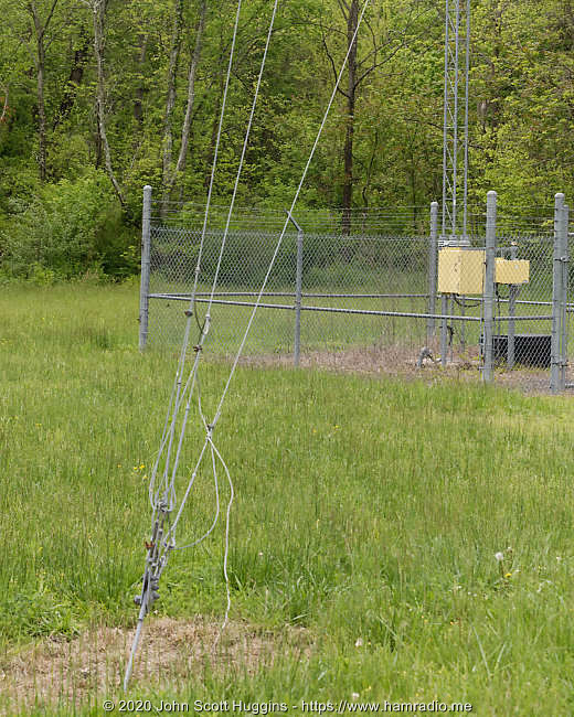
Guy wire ground termination
Eventually the guy wires re-connect with galvanized wire well away from the tower and terminate at the tie points with the usual grounding system.
Electrical analysis of this 351 kHz beacon
We can perform a basic NEC analysis with these guesstimates…
- Tower with nine sections including the lowest one comprising the insulators about 90 feet (~27 meters) tall.
- Top hat wires made from 45 degree guys about 60 feet (~18 meters) length.
- Assume 25 watts is available at the transmitter output insulator at whatever impedance this point really is.
- Assume the transmitter grounds to some earth rod plus radial field… I’ll just tie to MiniNEC ground for now.

The analysis below is ultra basic and only models the approximate lengths of perfectly conducting radiators of small diameter. It’s only here to show the purpose of the top hat feature and highlight the large voltage at the feedpoint. All that said, let’s proceed.
NEC Structure for low frequency beacon
Notice the top hat wires do a good job of of moving the low current, high voltage, tips away from the tower top to allow the vertical monopole to maintain good current magnitude (shown by the green lines) along the entire height. Hence the purpose of a top hat.
NEC Parameters for low frequency beacon
This is the voltage across the source near the bottom of the vertical wire (little magenta circle). Both the Voltage and Impedance values confirm this antenna is very capacitive. Despite the best efforts of the top hat, this antenna is still electrically short. A conjugate antenna matching system, the big yellow box, is essential. With only 25 watts, this simulation suggests the reactive voltage on the tower is very high.
NEC gain pattern for low frequency beacon
Bear in mind there are many parameters, specifically ones involving ground modeling and efficiencies, that play havoc with the actual real gain of this antenna system. The pattern below shows about a 3 dBi gain, but don’t hold me to this as I used the MiniNEC ground with zero ohms to earth. The pattern shape is probably a good representation of reality, however.
There is, of course, a ground wave element to consider as well, but this doesn’t matter much for this system’s primary aviation use. It does matter for my use of this beacon in testing of SDRs, antennas and such from my home. This beacon is ideal for checking MF reception. I hope it stays on the air.
A much better NEC analysis is possible with time. All I want to point out for now is the high voltage.
E-field measurements
Because I can, I made several spot measurements around the LF beacon along the gravel road at various distances from the radiating tower. I also generated E-field profiles from the NEC4 simulation for comparison using various ground conductivity and dielectric values from the 4nec2 choices. The graph below represents E-field values at 2.5 meters above ground level.

Though coming in a bit lower than simulation, my measured electric field values roughly follow what NEC4 predicts. The type of ground used for simulation changes the results a bit. For the purposes of this article, and given the rudimentary NEC model with its many variables, this is a reasonable correlation. For those with NEC4 and a desire to play around with your own simulations, here is the NEC file with a .txt added. Remove the .txt before simulation. Change the ground parameters to see what happens.
Key takeaways
The aviation non-directional LF/MF beacon is a good study of radio engineering. Despite its size, the 90 foot or so tower is an electrically small antenna problem that requires some thought to achieve a design win. In today’s world, cell phones have the similar problem of housing electrically small antennas for cellular, WiFi and soon 5G use. The problem for most tech aficionados is they never see and appreciate just what goes into making these devices’ compact antennas work. The aviation beacon is really no different, but is on a macro scale that provides a great view into the techniques one needs to prevail. Things we learn from this beacon survey include:
- Electrically small is electrically small no matter how you scale it.
- Top hats are the tried and true solution for increasing efficiency if and when you have the space.
- High voltage and capacitive reactance are the norm for electrically small antennas.
- Even though this beacon is only 25 watts, thousands of volts exist at the transmitter system antenna terminal and the tower above its insulating spacers. Forget the one hand rule… this requires a no hand rule… in fact just keep yourself far away from such installations.
- The primary radiator is galvanized steel tower with three galvanized steel top hat wires. No copper weld or anything fancy.
- This system is rugged, simple and plays (or played) an important role in aviation.
- Inside a fence for a reason…

Perspective for 630 and 2200 meter transmit
This beacon provides perspective for those who dare to transmit on these new low bands with electrically small antennas at almost any power level. Various stories of burned up insulators for the uninitiated suggest the trouble taken by the designers of this NDB station towards handling high voltage were prudent. May the lessons taught by these engineers and technicians inspire our use of 630 and 2200 meters.
Conclusion
Non-directional beacons have been an important navigation aid to the aviation world for many decades. The transmitting stations use AM modulation, or a close equivalent, with audio tone Morse identifier. By close equivalent I mean the possibilities proposed in this FAA document…
 modulation")
Here’s a view of the spectrum…

The spectral pattern suggests MSQ uses single carrier, double sideband amplitude modulation.
Here is audio kindly provided by K2PI.
It does one thing and it does it well. Progress is moving more of these stations to the scrap heap as satellite navigation push ground based systems off the air. However, as a pilot, the shuttering of the ground based systems in the face of easily jammed satellite offerings gives me pause, but that’s another story.
If you would like to see and appreciate an electrically small antenna in large form, go see, BUT DO NOT TOUCH, your local LF or MF non-directional beacon before its gone forever.
Oh, in case anyone might wonder, I never broke the plane of the fence to get these photos. Good cameras with good lenses make good photography possible.
Further reading list
- https://en.wikipedia.org/wiki/Non-directional_beacon#Monitoring_NDBs
- https://www.faa.gov/air_traffic/publications/atpubs/aim_html/chap1_section_1.html
- http://www.faraim.org/aim/aim-4-03-14-33.html
- http://www.tashkoo.com/Products/TASHKOO_NDB_Antenna.html
- https://www.classaxe.com/dx/ndb/rna/signal_list
- http://w8ji.com/ndb%20beacon%20fish%20buoy%20net%20beacons.htm
- http://njdtechnologies.net/hall-of-flame/
Revisions
- 2020-05-29 – Added e-field measurements and a refined NEC4 model. Added comments about 630 and 2200 meters.
- 2020-06-05 – Added FAA information about modulation. Added an SDR spectral plot.
- 2020-06-07 – Finalized tower height to the likely 90 foot value derived from counting nine tower sections and the note from a commenter below.
- 2020-08-31 – Added link to Hall of Flame
- 2020-09-01 – Fixed dumb spelling error. Thanks Saul.
- 2020-09-04 – Grammar and tweaks
Great write up! Really interesting subject and enjoyable reading. Thank you!
Beautiful and thoughtful post, John. MSQ has been a mainstay of my NDB dxing for several years now, and will hate to see it go off the air.
Excellent article. I have logged MSQ just once from here in NE 1192mi last October. Incidentally MSQ used to be CJR 251 and was apparently re-located to the present location. Also I have a note that says the antenna is 27.4m or ~90ft.
Nice profile of an NDB–Thanks!
What a great article; really enjoyed it. Thanks for writing it. I'm off to explore the rest of your site now.
Excellent and informative article. Simply explained! Thank you
Good to know I knew they were out there but have never looked into them. Thanks for the information! W8IP
Vy nicearticle, thanks. NDB listener from EU here…
Buena publicación, hermosa estación de AM, en relación a la protección de rayos a la salida de la unidad ATU (caja de sintonia) entre el aislador y la torre se agrega una espira de unos 30 centímetros de diametro, la separación del conductor y el descargador a tierra es generalmente 1 milimetro por kw.
Thanks Alejandro. For english readers, here is the translation from Google Translate…
"Good publication, beautiful AM station, in relation to the lightning protection at the output of the ATU unit (tuning box) between the insulator and the tower, a loop of about 30 centimeters in diameter is added, the separation of the conductor and the Ground arrester is generally 1 millimeter per kW."
Had "DE" 344 kHz in Madison Hts, MI decommissioned a couple years ago. It was in a playground area adjacent to a school. There were bike trails that went right by it. It used 3 parallel wires for the top hat, and the radiator was simply a wire that hung down, and went through an insulator into a wooden shed.There was also a 75 MHz corner reflector antenna for an outer marker. The corner reflector was removed and the wire radiator disconnected, but the remainder, including a fence, still stands.
Good pictures and write up. I used most of these principles for my 47 foot high 160 meter antenna. It has a large top hat which resonates the antenna below the band. Have also seen long wave BC antennas in Europe. My local aero beacon SQT went off the air permanently about two years ago to provide an additional highway interchange for I 95 at Melbourne, FL
Great article. I am with you, I don't like the dependency on satellite navigation.
This is a great article, thanks for posting it! Like Randy above, I'm also with you on not throwing your eggs in one basket with PNT and have been crying it to anyone who will listen ever since the demise of LORAN was announced over a decade ago–and we were proven right! Now eLORAN and friends are coming back along with improved versions of what can only be described as USA OMEGA and USSR (clone) ALPHA VLF systems using existing VLF transmitters.
Finally, you alluded to, but didn't point out the accidents those on 630m & 2,200m have had. It's called the Hall of Flame (not to be confused with the many fire fighter ones) and the link is here with MANY pictures proving your analysis above:
http://njdtechnologies.net/hall-of-flame
Well done! Excellent work! 73 de Bart Lee, K6VK ##
Great! However, I imagine your teeth were *clenched* and not "clinched".
Excellent all around, Thanks!! I have been a beacon hunter for many years (on radio, and driving to the sites) My first 'up close' beacon experience was on a beach, north of Chicago, fenced in but totally visible…. Spent a long time going over every detail. Again, Thanks for a great article
Frank, WA9CWX
I maintained UG when I was with FAA. It was an LOM, colocated with Waukegan Outer Marker. Had a hula hoop style top hat. It ran 30w and had over-the-air monitoring at UGN ATCT (Waukegan Airport.) It was my favorite site largely because of the private beach. I was often able to have my lunch on the rocks overlooking Lake Michigan. The equipment was ultra modern, but the site still had a rotary dial telephone when I retired in 2007.
Excellent article and an enjoyable read. Thanks.
I've heard a couple of aviation beacons which are not too far from the home QTH and I think you've just inspired me to go hunt them down!
I used a modified NDB transmitter on my experiments on 2200m in the 2000s that helped get amateurs in Canada the band. No you won't die instantly using these bands… You'll just be more likely to get painful RF burns… Ultimately needed to move away from vertical E-field antennas antennas and use a H-field loop to make the first QSO with Japan from North American on 2200m. http://www.arrl.org/news/first-2200-meter-ve-ja-q…
73 Scott
VE7TIL
Very interesting article. In 20 years with FAA, I maintained several NDBs in Alaska and Illinois, many of which are still operating. Three of them had antenna failures. One was ET, a LMM (Locater Middle Marker) at the Bethel Airport. It was a 3-wire array like the one David Riley described, and came down in an ice storm. Another, near Galena Air Base, was a self supported tower that fell into the Yukon River when the river eroded its base. A third, near Nenanna toppled due to permafrost. The monitor for this one was still receiving the beacon with the tower lying on the ground. We had pilot reports of a weak signal, and when the technician arrived he had trouble finding it with no antenna to see.It was relocated. and later decommissioned.
MSQ is widely heard, I've heard it here in S. AZ.
Steve AA7U
Nice work! Thank you.
Dave, AB3MO voluntarily grounded pilot
Love using these for band conditions on 160. I am old enough to remember tower beacons sending more code. PNT at Pontiac il. Was my favorite. Ment I was almost home.
At least one list says that the Culpeper NDB is decommissioned, but I'm pretty certain I'm still copying MSQ on 351. As a local, can you confirm that it's still beeping? 🙂
As of October 26, 2022 still loud and clear just north of the beacon.