While planning for a ham radio hike into the mountains to support the Appalachian Trail Golden Packet exercise, I asked my club members for ideas about a good portable 2 meter antenna.
One response included a link to this web page showcasing a collinear J-Pole antenna using two 5/8ths wave antenna elements.
As soon as I saw the site I thought, “Oh no… not another 5/8th wave antenna discovery.” However, to my surprise (and very much unlike the regular 5/8ths J-pole which does not work well at all) the two 5/8ths sections yielded a reasonably symmetrical pattern in both free-space and over real ground at a similar height. Feeding issues aside, at least this design passes the threshold of physics.
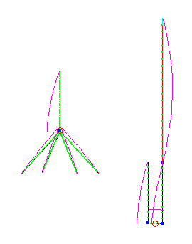
So let’s compare the relative merits of the 5/8ths collinear J-Pole by first introducing the contenders…
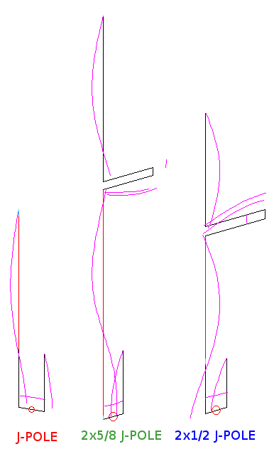
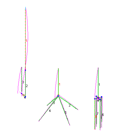
I added a regular J-Pole to compare each collinear design against.
The free-space simulation, below, of the buck0 design does show a high takeoff angle compared with a regular J-Pole and a double 1/2 wave collinear J-Pole often called the Super J-Pole.
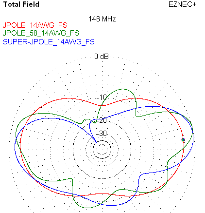
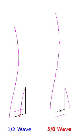
Freespace EZNEC simulations are often practical, but what we care most about is real-world, just above the Earth, simulations. Below are the same three antennas with their bases about 360 inches above real ground in EZNEC…
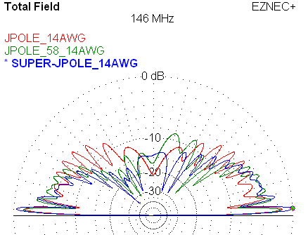
This is more like it. Note the collinear 5/8 wave J-Pole does, indeed, perform about as well as a regular J-Pole in these circumstances at this particular azimuth. The half-wave collinear J-Pole beats out both antennas by about 2 dB. Here is a closeup of the lobes on the right…
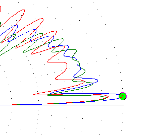
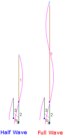
The buck0 5/8ths wave collinear J-Pole does perform. However, if I take the same #14 wire, use the same cool construction techniques, but make a traditional 1/2 wave collinear J-Pole with the feed-stub, a half-wave section, a quarter wave stub topped off with a final half-wave section, the antenna is a good 2 dB stronger than the double 5/8 j-pole from buck0 in over-Earth simulations at about 3 degree elevations in all directions.
Plus if you build a regular J-Pole with #14 wire you will do about as well as the more complex buck0 design.
Less wire… simpler feed… more gain… who knew.
At least the Collinear 5/8 Wave J-Pole works, but it seems clear with the admittedly simple EZNEC simulations above, your wire investment is better spent on the simple traditional 2m meter J-Pole or the Collinear 1/2 Wave (Super) J-Pole.
Have fun with your J-Pole, but don’t forget to choke off the feed-line and mounting mast RF currents.

HI read your comment on 5/8 wave, I strongly suggest you undertake some real
"field" trips with real tests and put your computer away. . Here is what you will find using a single 5/8 local signal will be much stronger. Distant fringe signals will be somewhat stronger. I have never found a stub stacking 5/8 or 1/2 . arrangement working without it adding a rather large Horizontal component to the pattern. Try it set up say 4 mobiles at various distances
or measure out repeater distances and use them Use a 1/4 ground plane as your
reference antenna and measure out your S meter into micro volts. By the way a 5/8
radiator can be easily matched with a gamma rod. no coil tapping required. Like the hams know 5/8 lowers the take off angle over a 1/2 or 1/4 wave. add the radials and no Choke coil required.
sorry, my saying OH "NO" Another J pole..
Hi Stan and thanks for the comment. I have no doubt what you witnessed, but that says more about your entire installation, not just the antenna. The physics involved doesn't change. As 5/8 wave antennas go, unfortunately "what hams know" is often not so.
Hi,
Very interesting. However I have a question based on real terrain data and simulations with the ICS Telecom radio-planning tool.
For a hilly profile, 147 MHz, about 43 Km, with a dominant obstacle about 1/3 of the total distance, what would be better :
Some kind of colinear antenna, with a vertical 15 deg radiation pattern or a similar gain yagi with its 50 + deg vertical pattern ?
I tried both a 4 element yagi and an ARX-2 Cushcraft without any clews…
The two sites are at 250 m. and 22 m. elevation respectively.
Two joined 5/8 antennas are not other that an extended zepp antenna when fed to the center. This antenna is known to have higher gain than a normal half wave dipole. In the colinear configuration here represented you need a phase inverter at the center and an adapter at the bottom to tune it. It should be electrically equivalente to the double zepp, but with increased antenna height due to the matching section.
A balanced feed-line cannot feed a 5/8 antenna, colinear or single. The reason is that the feed-point impedance of a 5/8 antenna is <400 Ohms, and this means that the balanced transmission line of the U section of the J-pole is no longer balanced because it has a low impedance on one side and therefore would radiate. While the collinear 1/2 wave is good, an even better radiation patter could be achieved by hanging a center-fed full wave antenna, fed by a 1/4 wave stub: __n__ to hang vertical is a mechanical challenge for 10M and below, but the radiation pattern is better than the phased stub 1/2 wave antenna shown above.