A friend of mine is preparing for the upcoming Virginia QSO Party in March 2009. Part of the preparations include a focus on some good VHF antennas to support the heavy use of VHF mobile operations in this party. Vertical polarization is key to success. He spoke of a 5/4 Wave Antenna.
Unfortunately, one web site promoting a 5/4 wave antenna solution failed to realize you can’t make an antenna longer without eventually hitting a limit.
During commute time repeater discussions my friend was contemplating the use of a 5/4 wavelength vertical for his VHF antenna. He mentioned a web site with the construction details for just such an antenna which results in a nice simple no fuss vertical antenna housed in a PVC enclosure. Great, I thought, but I had some concerns over this whole 5/4 wavelength thing. I told my friend I would work up a simulation to see how good this antenna is. The first step was to find the web site containing the construction details for a 5/4 wave VHF antenna. This was easy resulting in this web site…
The author provides superb details on how to construct the 5/4 wavelength VHF antenna. He wisely predicted the installation into PVC would change the speed of light of conductors within. He revealed the need for a matching network. Good so far. In fact, I bet this antenna design provides a good match to 50 ohm coaxial cable, is of sound construction and will last many years in the elements.
However, that’s only part of the story isn’t it. How will the antenna actually perform.
Cebik’s article series on J-Poles[1] alerts us to potential issues saying in the “Longer is Not Necessarily Better” section…
“Over the years, I have heard many suggestions for improving the standard J-pole’s performance by simply making the radiator section longer.
[. . .]
Unfortunately, none of these ideas promises much when modeled either in free-space or over ground.”[1]
Let’s try EZNEC ourselves to see what Cebik spoke of…
While it is time consuming to simulate all the wire size and dielectric constant details the candidate 5/4 wave antenna offers, we can make the following assumptions and model accordingly…
- Since there is a parallel line component about 1/4 wavelength long, this is really an end fed full wavelength antenna with the extra 1/4 wave portion acting like an impedance transformer just like a J-Pole
- The existing models of J-Pole antennas from Cebik’s excellent NEC antenna simulation collection provide just what we need to start analyzing the full-wave antenna
- The 5/4 wave “tall” antenna will be compared directly to the 3/4 wave “tall” J-Pole
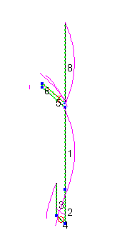
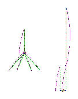
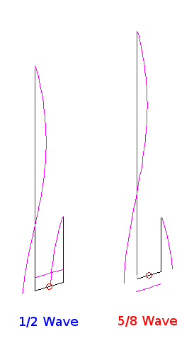
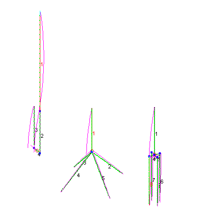
Both antennas are modeled with 18 AWG wire, used by the web site author for most of the vertical element, with the horizontal portion 300 inches over EZNEC’s “Real/High Accuracy” ground. Here they are with their RF currents shown…
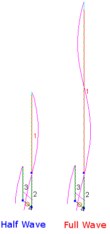
Those in the know will already spot trouble with the full wave radiating element. Those RF currents do not result in more RF radiation in the horizontal plane, but rather help to cancel it. For those of you experimenting with EZNEC be sure “Current Phase” is selected in the View Antenna options so you will see the vector, not just the magnitude, of the currents on the antenna view. You also need to ensure all your wires go in the same direction with end 2 connecting to end 1 of the next wire or the current phase might show incorrect vectors; The RF simulation plots work perfectly with wire direction either way, however.
Here is the full wave plot in red compared with a simple half wave J-pole in blue…
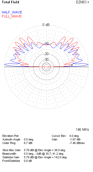
Recall both antennas are simulated with the base 300 inches above ground with the following discoveries:
- The full-wave vertical is at least 7dB worse than the regular J-Pole at 4 degrees elevation – important for base to mobile and most any VHF communications
- The full-wave vertical shows negative 1.67 dBi gain at the terrain hugging low angles
- The full-wave does provide move energy at high angles which might be of benefit for base to air communications
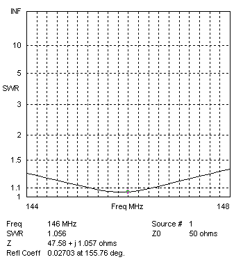
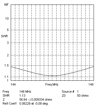
I ran SWR calculations for both antennas and they both offer an excellent match to 50 ohm cable throughout the 2 meter band. For completeness here they are…
What are we to draw from this?
First, great SWR does not a good antenna make.
Second, the full wave antenna does not, by itself, provide any benefit for terrestrial radio use and is, in fact, detrimental.
One can ask, though, how is it taller antenna designs provide better radiation towards the horizon.
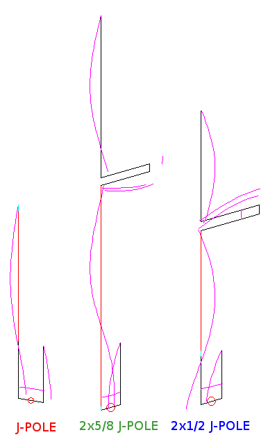
The answer is based on the idea of making the RF current peaks in the antenna be in the same phase so the energy, towards the horizon, adds rather than subtracts. Many methods exist to achieve this, but one popular technique is to add a half-wave delay between the two half-wave antenna portions. By doing this we cause the current in the top antenna to be a full 360 degree delayed from the current in the bottom and, thus in phase. This technique results in a type of antenna generally called “Collinear.” The figure below illustrates how this is achieved in the popular Double J-Pole antenna…
Plenty of web sites exist to show how to build a Double J-Pole antenna so we won’t go into that here.
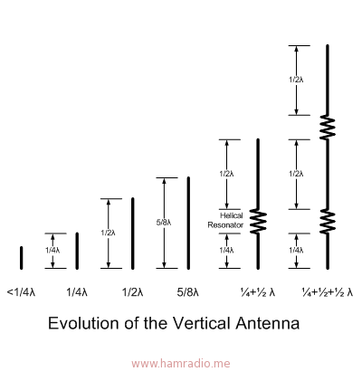
The UHF antenna on your vehicle may well have two or three antenna sections arranged as a collinear antenna with half-wave delay coils between each section to keep each radiating in phase. If we look at the evolution of the vertical antenna…
…we see 5/8 wave antennas tend to be the upper limit of length before phasing techniques need to be applied if we are to keep a good signal towards the horizon. Collinear antennas are a tried and true approach for antennas longer than 5/8 wave. Whether a hairpin or helical resonator is used to phase the 1/2 wave antenna “pieces,” improved performance awaits the antenna builder. As we any good thing there are diminishing returns by adding more co-phased antenna pieces.
The 5/4 wave antenna discussed is really a full-wave antenna with a 1/4 wave feed. The lack of an additional half-wave delay element between the two high current portions of the antenna suggest the author has missed an important detail in antenna design which will render the antenna far less useful than anticipated.
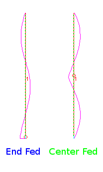
It is likely the author confuses his desire for a single wire antenna with dipoles of similar length – the extended double Zepp type is an example. The difference between an end fed piece of wire and a center fed dipole is, again, the current phases. A center fed dipole pushes current in one wire while pulling on the other thereby ensuring each dipole leg has current in phase – assuming the dipole legs diverge from the feed-point of course. This cannot happen in an end fed single wire one wavelength or 5/4 wavelength long without some means to delay the half-wave portions by 180 degrees.
However, the author’s noble attempt at antenna design and excellent construction techniques remind us there are other ways to apply his ideas to realize the suspected intent; A desire for a good sturdy Collinear antenna.
A final note worth considering is this… Can EZNEC or any antenna simulation program provide good enough results to use for antenna comparisons? Of course, but there are limits. If you are trying to see if one antenna is a dB or so better or worse than another you do need to be careful with the assumptions you put into your simulation. However, comparing a half-wave antenna against a full-wave antenna, both end fed with a 1/4 wave section, is well outside almost any margin of error so you can expect the full-wave antenna antenna to be far worse than the half-wave for horizon coverage based on the simulations above.
Have fun with your J-Pole and don’t forget to choke off the feed-line and mast RF currents.
References:
- Cebik, L.B. “Some J-Poles That I Have Known – Part 4“. www.cebik.com. Jan-Feb 2002.
Why do you assume he wants a colinear antenna? I use the 5/4 wave for repeaters and it outperforms your center fed antenna BECAUSE of the high angle of radiation, not in spite of it!
Your correct Keith… I really don't know what the maker of the 5/4 wave antenna design wants. The only operating parameter his web page discusses is gain…
"Although not actually measured, this antenna should give at least 6 dB gain if mounted high enough."
I do assume the phrase "mounted high enough" reflects a desire to provide better performance towards the horizon. Assumptions aside, the 5/4 wave designer doesn't really say what the antenna is good for… thus the stimulus for this article.
If, as you suggest, the designer meant to focus energy to high elevation angles at the expense of terrestrial service, he definitely achieved this.
Finally your assertion high radiation angles make for good repeater use is counter to the trigonometric realities you are either very close to the repeater and don't need much gain at any angle or well away (often just a couple miles or more) and need gain with low radiation angles. A high gain, high angle antenna has little use in typical repeater service.
Wouldn't just a 1/4 wave have the same gain at that angle of radiation and be much simpler to build and maintain? When you put them both on EZNEC the 1/4 wave seems to be similar enough to the 5/4 wave at both low and high angles not to warrant the effort. Now if you put a 3/4 wave antenna, no phasing, up you seem to get the best of both worlds. EZNEC shows that you get a very good low angle of radiation with high gain similar to a 5/8 wave and also a high angle of radiation similar to the 5/4 wave. No extra parts and much simpler to build and maintain. Kind of like a cheep dual band 2m/70cm antenna design. Something to think about when the wind blows and the neighbors complain.
Qual o segredo similiar a evolução das antenas para fazer uma 2x 5/8; 3x 5/8; 4x 5/8; 5x 5/8 e quanto 5/8 de onda quisermos ?
Any antenna element more than 0.6389 wl long or 230° electrical wavelength
will be a sky wave antenna…
Thank you for sharing this info. I replaced a good 2m ground plane with a 5/4 vertical and was sorely disappointed with the resulting performance for hitting area repeaters,some close to 50 miles away. I discovered your page while in the process of trying to figure out what I did wrong. I will now look into double J-poles versus building another 5/4.