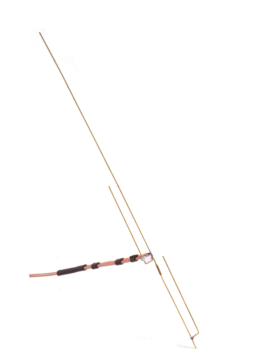
Type “J-Pole” into any search engine and you will see dozens if not hundreds of plans to build your very own J-Pole antenna. Many are variations on the tried and true 1/2 wave design with the 1/4 wave stub at the bottom. Be it a plumber’s delight with copper pipe or ladder line heaven using a trimmed up 450 ohm feed line, many folks have successfully created their own J-Pole antenna with a surprising variety of materials.
However, there appears to be some kind of mystical attraction to the 5/8 wave radiator. Several of the J-Pole designs attempt to make the radiator 5/8 wave in length and adjust the phasing stub to make for a good match.
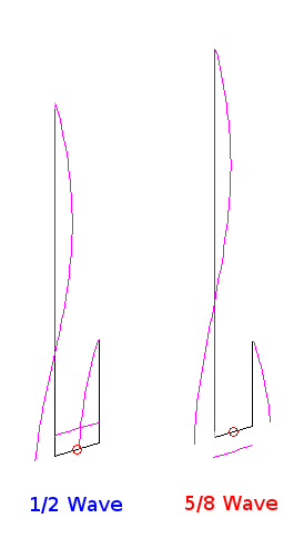
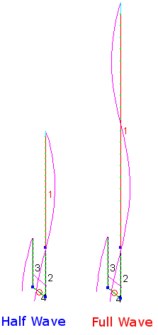
Let’s compare the two approaches using the models available from the late Larry Cebik’s NEC collection. Here are the contenders each using 3/8 inch diameter copper pipe…
The current magnitudes resulting from the simulation are shown to reveal just how current flows in the conductors and, just as important, their polarity.
J-Pole fanciers already understand the 1/4 wave stub in the bottom part of the antenna, the J, have roughly identical and opposite currents which tend to cancel any radiation effects. This is very similar to ladder line when and if the currents are equal and opposite. Of course, where the 1/4 wave stub meets the bottom of the 1/2 wave radiating element current is not zero or no power would travel up to the radiator. This results in a slight imbalance in two currents.
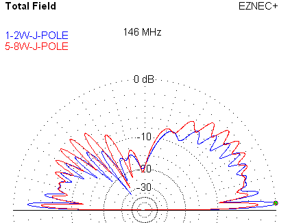
The plot below shows the azimuth plot of the signals from both antennas. The 1/2 wave plot is at about 2.8 degrees above the horizon while the 5/8 wave peaks around 2.6 degrees. Each antenna is simulated with their base 360 inches over real ground.
Both antennas exhibit asymmetry due to their 1/4 wave phasing stub small imbalance. The 1/2 wave J-Pole beats the 5/8 wave J-Pole by about 2 dB.
Here is the elevation plot of both antennas along the worst case azimuth bearing…
The asymmetry of a J-Pole antenna really comes to light here with a clear bias towards one side of the antenna. Note the 5/8 wave J-Pole has more energy at higher elevations at a cost of energy on the horizon where we want it.
So what are we to think about the extra copper and less balanced approach offered by the 5/8ths Wave J-Pole antenna?
My conclusion is you are better off sticking with tradition and build the 1/2 Wave J-Pole antenna.
A reasonable question is why isn’t 5/8 wave better. 5/8 wave is about the limit a vertical radiator can be to peak up gain towards the horizon. However, it assumes you have a very robust ground system to work against. A J-Pole has no such ground plane.
Another problem comes from the fact the 5/8 wave j-pole has that unbalanced current in the J part of the antenna. Thus the length of the antenna, electrically, is really something other than 5/8 of a wavelength. Such is not the case with a 5/8 whip over a good ground system.
5/8 Wave antennas have their place, but the term is used far too loosly in amateur radio circles. The J-Pole is one good example where deviating from tradition yields a functional antenna, but one with less performance than the simpler of the two antennas.
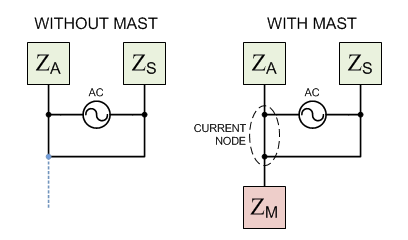
If you are considering building a simple J-Pole great! Build a 1/2 Wave J-Pole and don’t forget to choke those feedline and mast currents.

Hello
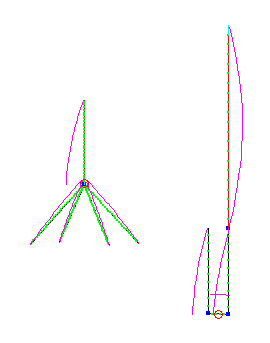
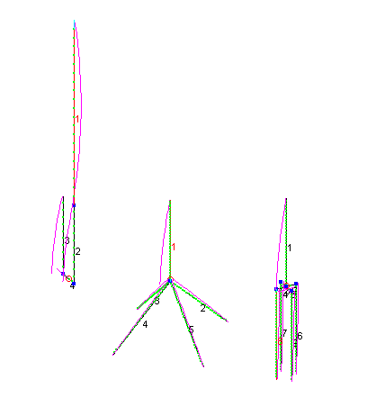
try add 1/4 wave radials to bottom of J-pole point and re-run results.
Ive been experimenting using ground plane radials at the bottom point of the J-pole to see what effect this has as a artificial ground plane to work against,
Just some experimentation but was interested if 450 ladder line could be used at a 5/8th version,I do know or suspect adding 4 radials cut at a 1/4wave wavelength for 5/8th may give you a lower angle of radiation?
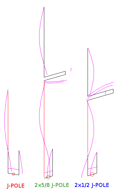
Worth a go,im not really into software modelling antennas but maybe you could give it a go and see what results spring up or can it be modeled?
Regards
Rob