W. J. Lattin patent from the late 1940s
Check out these figures by W. J. Lattin proposing decoupling stub methods in his 1950 patent US2535298…
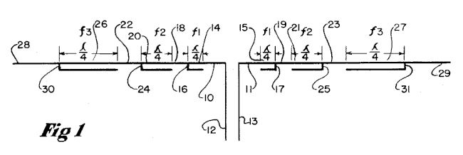
No doubt this served as inspiration for many including the latest crop of rollup, dual-band J antennas typically designed for 2m and 440. A quick read of the patent details certain restrictions on how close the next lower frequency can be. However, no words suggest wire beyond any given stub need be anything special. Recent work with some of the rollup dual-band J antennas suggests there might be a problem.
Do quarter-wave stubs work alone?
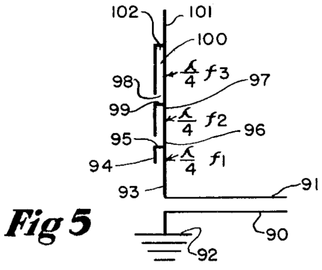
I checked what NEC has to say about the topic featuring thin wire models of a dipole terminated in a pair of quarter-wave stubs. The initial model is simply this in the following figure.

To this I added wire in increments that forced various standing waves at the shorted end of the quarter-wave stubs. The current-with-phase feature is turned on in 4nec2.
- Figure 4A is the initial model with very short wires protruding past the stubs.
- Figure 4B shows the current magnitude and phase with the middle portion showing a strong half-wave. The stubs contain equal and mostly opposite currents. The pattern isn’t shown since we are focusing on current, but it has the classic doughnut shape.
- Figure 4C extends the extra wires 1/4 wavelength beyond the stubs.
- Figure 4D extends the extra wires 1/2 wavelength beyond the stubs.
- Figure 4E extends the extra wires 3/4 wavelength beyond the stubs.
- Figure 4F extends the extra wires 1 wavelength beyond the stubs.
What’s interesting here is the stubs only perform their current block role when the conditions past the stub are favorable. In this case 4B, 4D and 4F have reduced current while the others see little benefit from the stub.
Compare to currents along a wire
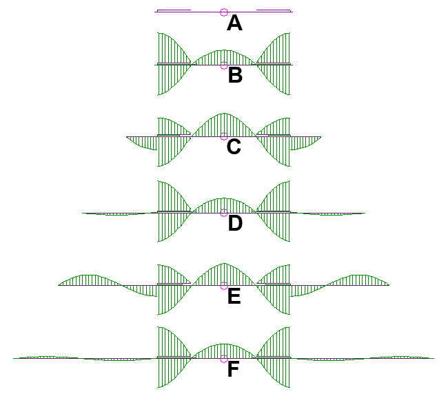
By comparison let’s look at the above model with the parallel stub wires removed.
It should come as no surprise the antenna wire simply has the standing waves at all lengths. So it seems the quarter-wave stubs pioneered by Lattin do help tame antenna currents beyond the parallel wires. However, this is true only when the remaining wire presents the right conditions.
Seeking impedance discontinuities
Let’s look at figure 4 once again with some new information.
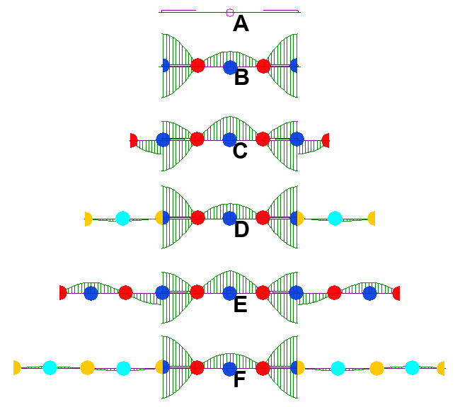
Looks rather festive doesn’t it. Let’s explain the colored dots.
- The Blue and Cyan dots denote points of low impedance (the ratio of minimum voltage and maximum current) where Blue is lots of current and Cyan much less.
- The Red and Amber dots denote points of high impedance (the ratio of maximum voltage and minimum current) where Red is lots of voltage and Amber much less.
- The actual value of impedance of a single wire may be calculated. However, for the purposes of this analysis, high and low monikers suffice.
- Each circle is actually two semicircles divided vertical to represent the conditions to the left or right of circle center.
- All wires end in a semicircle.
Where impedances match
If we now look carefully at figure 6C we see the the blue dots at the outer most portion of the stubs tell us this point between the stub and the remaining wire both share a low impedance. The outer wire creates this condition, of course, by transforming the high impedance at the wire’s end to a low impedance by virtue of it being 1/4 wave in length. Hence, impedances thus matched, there is little reason power cannot continue to flow outwards towards end of the antenna.
The same holds true of the situation in figure 6E as the wire ends are 3/4 wave in length and present the ideal low impedance to the tip of the quarter wave stub.
Where impedances differ
The circumstances in figure 6D and 6F reveal the desirable choking action thanks to the end wires presenting a high impedance connected to a low impedance. Thus mismatched, less power may flow. As well it is not unreasonable to think of this as a high blocking impedance at a low impedance point. This is what you might think of when using ferrites to choke common-mode current on a feedline. The very short, open bits of wire at the ends of the antenna in figure 6B may also be considered an impedance mismatch… open-wire vs. low impedance point.
What this means
It seems what is past the various chokes in Lattin’s patent matters if the chokes are to perform their task. He proposes a multi-band HF antenna for the amateur radio bands which are harmonically related… perhaps in just the right way to avoid the problems identified above.
Figure 6C highlights a worst case condition for the situation where one desires a dual-band antenna with the higher band operating at a 3rd harmonic. Such appears to be the case with several of the rollup 2m/440 J antennas with integral coaxial 1/4 wave chokes.
Conclusion
Lattin’s patent is well worth the read for the above and some other interesting design tricks to obtain multi-band performance. Whether or not he knew about the dependance between choke and outer wire isn’t clear in the patent specification. I can only hope he made an actual model of his invention to his liking.
Modern users of coaxial chokes in antenna radiators are well advised to simulate their final design in modern EM simulators. NEC, for example, seems quite capable of spotting trouble. Its scorecard for analyzing and predicting the ability of the mast decoupling stub in the patent pending J antenna improvement is 100%. NEC isn’t perfect, but for this it seems good to go.
