Abstract
Few can miss the marketing of various rollup J-pole style antennas. Operation at their fundamental frequency (often 2m) yields pleasing results. Some feature a quarter wave stub inline with the main radiator that purports to “trim” the 3/2 wavelength at the 3rd harmonic. Several articles detailing such techniques appear in the annals of QST and other amateur radio publications. Inexplicably, the test results seen in these articles lack sufficient detail to come away with a “hey it works” conclusion. Independent exploratory tests and simulation suggest the quarter-wave ‘chokes’ fall short of the designers’ intent. Hence operation of these “dual band” antennas at the higher frequency offers little benefit for the added cost. The good news is all these antennas work very well at the fundamental.
Want to know more? Take the plunge into real measurements and simulations below. The article ends with an alternative design idea for the roll up J antenna.
Some rollup antennas under test
Figure 1 shows some measurements taken of several rollup J antennas: one traditional J and the rest SlimJIMs.
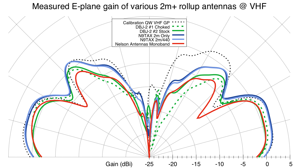
Despite help given one model with an additional ferrite choke, all perform pretty darn well. Two clear groups emerge…
- The heavier conductor models also with thicker coax essentially matched the gain from our reference quarter-wave ground plane type antenna with downward radials.
- The two lighter conductor models trade a bit of efficiency for supreme compactness.
The pattern shape for all match expectations differing only in efficiency almost certainly from feedline and antenna conductor diameter. This is a good trade space and these rollup antenna products offer choice to the buyer.
What about UHF performance?
The same cannot be said for UHF performance as seen in figure 2.
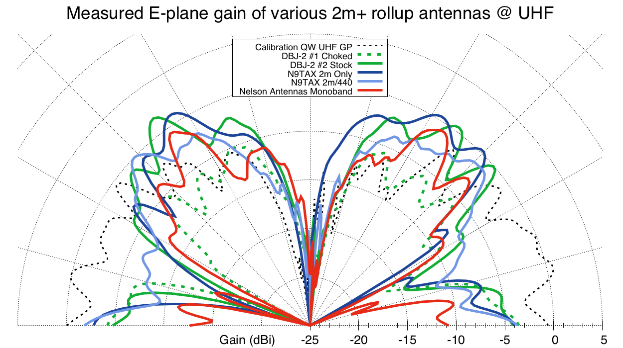
How many of these antennas beat a 445 MHz quarter-wave groundplane antenna? None. All have the typical monopole-operating-at-its-3rd-harmonic behavior. In fairness only antennas meant for dual-band use should have such expectations placed upon them. As many know, most any antenna can operate at harmonics of its fundamental frequency and such is the case with some of these models. The above tests reveal a much longer story than can be told in this article. For now let’s focus on the two models that try to modify the pattern by including an inline decoupling choke formed from coaxial cable.
First, though, let’s boot up on some J antenna characteristics.
Review of the J antenna voltages and currents
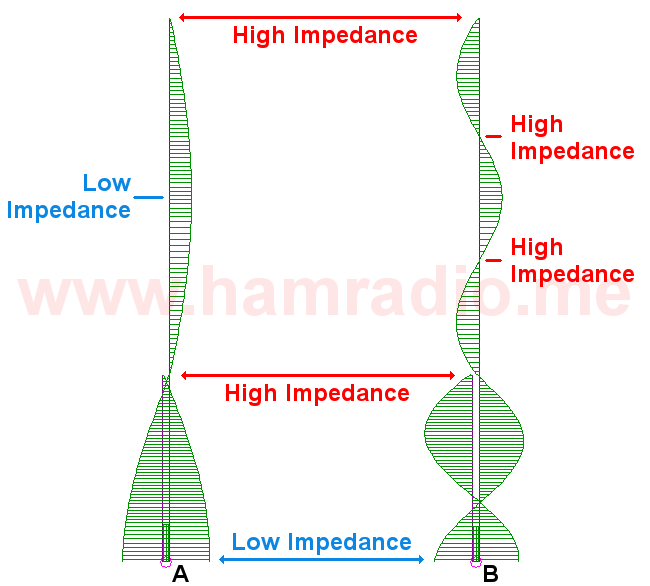
Figure 3 reveals the traditional J antenna with current magnitude and phase shown for operation at the fundamental (figure 3A) and 3rd harmonic (figure 3B). Indicators highlight positions of relative high and low impedances. The two “High Impedance” and one “Low Impedance” labels down the middle of figure 3 highlight impedance extremes shared by both modes of operation. Those who appreciate the artistry of Red Barchetta will understand the mechanical analog of this phenomena.
Verily the J antenna operates much like any resonant antenna system with two components: half-wave radiator (the standalone wire) and quarter-wave impedance matching system (the J). Despite the different circumstances for operation at the fundamental and 3rd harmonic, a compromise feedpoint for both, say 50ish ohms, along the quarter-wave impedance matching section is available. And that’s exactly what several “dual-band” rollup antenna manufacturers achieve.
Review of J antenna E-plane gain patterns
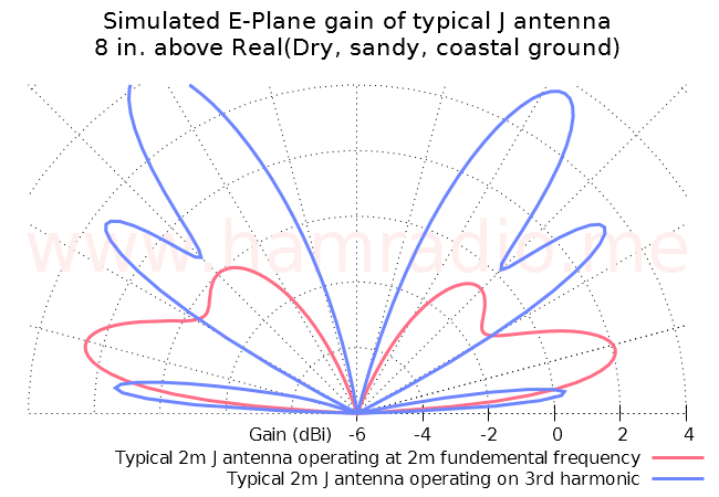
Figure 4 reveals the patterns from the above ideal antenna proportioned for the 2m band in both frequencies of operation: fundamental and 3rd harmonic.
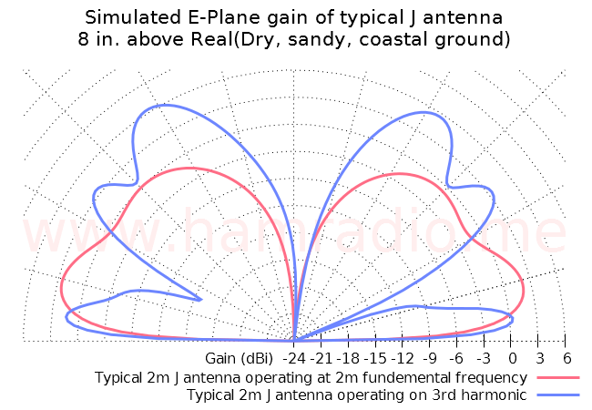
In this and all the following simulation patterns, the J antenna looks just like the letter J with the extra stub to the left. Hence the red trace shows the expected response at 2m with the characteristically noticeable, but inconsequential, gain boost towards the left.
When energized at 445 MHz with the current profile of figure 3B, the antenna exhibits the typical, almost long-wire, behavior of any 3/2 wavelength aerial. Since this simulation is over ground, we have most of the energy at high angles. There is still some performance towards the horizon, but certainly less gain that what might be possible with suitable modifications to the overall design.
All too often we tweak antenna designs to obtain a dB or two here and there. That’s the case with this analysis. Therefore lets take figure 4 and adjust the gain scale to help emphasize the subtle changes.
For the “every dB us sacred” crowd, figure 5 provides useful insight.
By the way, there is nothing special about the choice of “Dry, sandy, coastal” ground or the 8 inch height. I just picked something that give meaningful graphs and kept it constant throughout the simulations.
Enter the quarter-wave isolation stub
What if we could introduce design elements to ensure a half-wave length of wire at the fundamental only energizes one third of the wire at the 3rd harmonic. That’s exactly the design proffered by a few antenna designers. Figure 6 shows an idealistic mockup of one such technique using a bit of transmission line inline with the antenna wire so arranged as to act as a quarter-wave transformer.
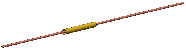
Figures 7 and 8 highlight the open and closed end of the transmission line.
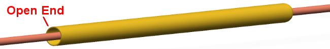

Thus arranged, the open end should harbor a high impedance given the other end is a direct short thanks to the quarter-wave electrical length and the principles of transmission line transformers. Of course in practice one uses some bit of real coax or parallel transmission line for this feature, resulting in a shorter device thanks to velocity factor. So take the above as an analog to what is actually practical. I’ll say this though… the ratio of the dimensions of the wire and shell are, in fact, proper for 50 ohms since in the world of CAD, it’s easy to show the real deal. Perfectionism… not enough because I’m sure that dipole length should be reduced for the fundamental, but oh well.
The quarter-wave stub applied
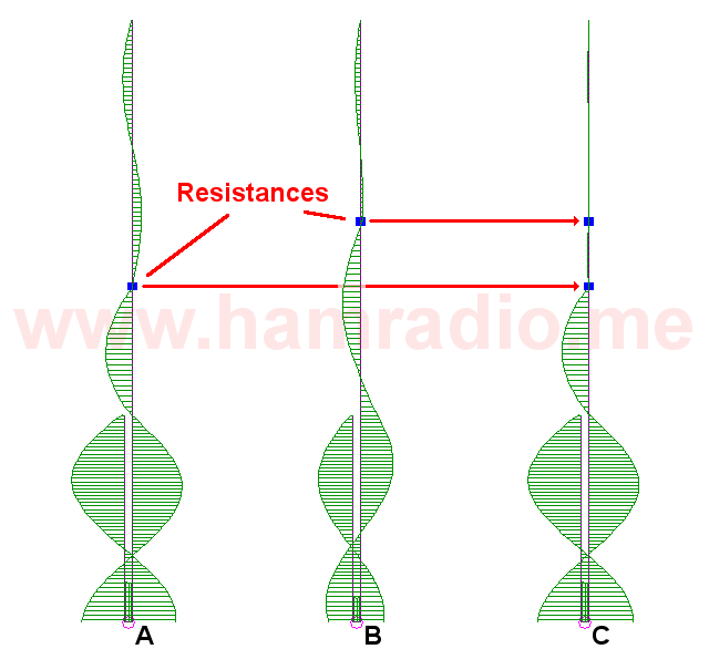
NEC is often a difficult tool to model the effects of transmission lines without careful effort. This is a good time to take a step back. Rather than simulate the minute details of an actual quarter-wave choke in a NEC model, let’s just assume it is moderately victorious in its goal. If this is true, then the choke places an impedance in series with the radiator at its open end. Inline resistances in series are very easy to model in NEC. That is what I did for the simulations below. Figure 9 reveals the models used to analyze the choked radiators operating at the 3rd harmonic of the fundamental frequency.
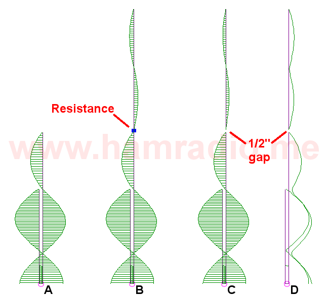
Figure 9 simulates various scenarios.
- Figure 9A reveals the hope and goal of designers using an inline whatever to make the wire above essentially disappear.
- Figure 9B simplifies things a bit for simulation by assuming the choke does indeed place an impedance (resistance in the model) in series with the radiator wire.
- Figure 9C assumes the choke wins the lottery and completely breaks the wire, but presents the real situation the wire ends are still near each other. Because the resulting current phase of the isolated wire section is neither 0 or 180 degrees (wraps around the upper radiator a bit), figure 9D shows the scaler magnitude to provide a proper comparison of all currents along the wire.
The series resistance of figure 9B is 10,000 ohms for the simulation. Other values produced interesting small variations, but for this article 10k and the open circuit of C and D were enough to make the ultimate points. However, let’s not get too ahead of ourselves. Let’s have a look at some E-plane gain patterns.
Properly defining pattern expectations
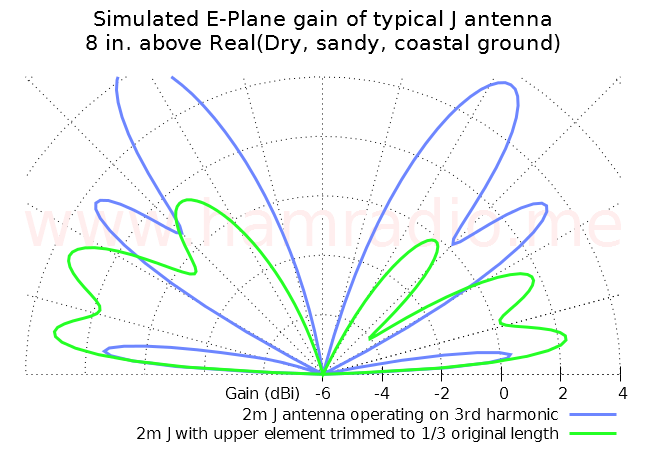
Figure 10 sets best and worst case limits. The blue trace is the same blue trace from figures 4 and 5 with the 3/2 wavelength antenna. The green trace is the response of configuration figure 9A showing the best it can be with the upper wire simply missing.
Okay so here we go…
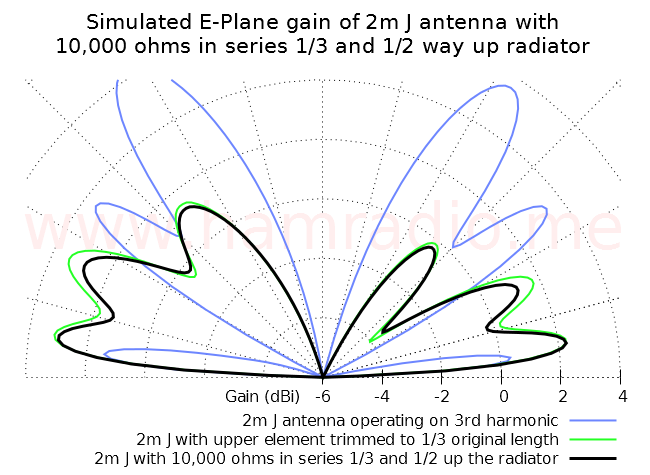
Series resistance of 10,000 ohms
With the best and worst plots defined by figure 10, we move to figure 11 with previous plots in thin lines to showcase and compare new data in thick black lines.
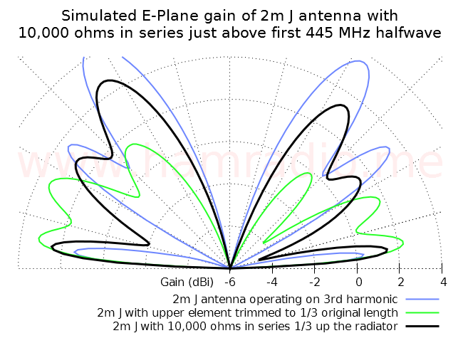
The series choke does help improve the response towards the horizon. This jives with the measured gain data of figure 2. Still some current remains in the upper radiator and prevents the pattern from achieving the behavior of the perfect short radiator. The result is a waste of energy at high angles.
Series resistance replaced with a 1/2 inch gap
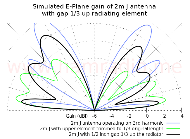
Even the perfect case of splitting the wire yields no practical improvement over the direct resistance. It seems no matter how well the choke performs its task, something else bleeds rf energy across the gap. Any progress towards a dual-band solution requires understanding of just what is going on in and around this gap.
The smoking gun
As the stubborn currents above the choke shown in figure 9 foretell, there appears to be another form of electrical coupling that mates the two wire sections we desire to isolate. All this regardless of how well the choke might function. What might the culprit be?
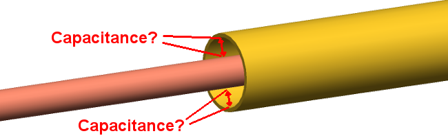
Figure 13 reveals a pest called capacitance in parallel with whatever blocking impedance the coaxial choke might provide. Couple this (pardon the pun) with the unfortunate happenstance of this capacitance, along with more than a little bit of cylindrical capacitance, at the high voltage points where this coupling is most effective… and the goals of decoupling are compromised. The fact this capacitance can so efficiently couple the wire tips across a 1/2 inch barrier is testimony to this reality. This “leakage” exists in the simulation currents of figure 9C and 9D along with the resulting gain pattern of figure 12.
Bummer.
Thanks to leakage capacitance we can never fully prevent the currents from flowing past the choke despite its performance. That, my friends, is one fundamental problem with chokes placed at the high voltage points along any wire carrying rf current. This includes feedlines, masts and, of course, J antenna wires.
Is there a better way?
One significant finding while patenting a solution to the J antenna’s propensity to conduct rf current down its mast is to place the high impedance choke at a low impedance spot along the antenna wire. We test this idea in Figure 14.
- Figure 14A – Original choked J antenna from before with “resistive” choke 1/3 up the radiating wire.
- Figure 14B – Same antenna with choke moved to the middle of the second halfwave of the 3rd harmonic. Not very effective and not at all conducive to proper tuning. The overall phasing of the antenna is a terrible mess.
- Figure 14C – Same antenna with the combination of chokes from 14A and 14B yielding greatly reduced current.
Let’s check on the pattern for figure 14C.
Well alrighty then… At last we close in on the ideal maximum possible gain using the combination of two chokes. An achievement? I suppose. One has to wonder if we are fighting the wrong battle in trying to eliminate the upper current.
Is there an even better way?
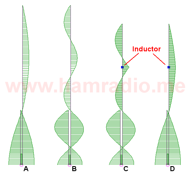
- Figure 16A – Typical J antenna operating at fundamental frequency.
- Figure 16B – Typical J antenna operating at 3rd harmonic.
- Figure 16C – J antenna with inductor in series midway up the radiating section operating at the 3rd harmonic. The first and third halfwave current peaks are in phase while the inductor reduces the anti-phase middle peak a bit. This is much like other functional collinear antennas designs.
- Figure 16D – J antenna with inductor in series midway up the radiation section operating at the fundamental frequency. The current profile is a touch more trapezoidal thanks to the inductance and shorter overall length.
The length of the radiating section and value of inductance were optimized in 4nec2 to yield an acceptable feedpoint imaginary value near zero ohms. You can see a bit of phase imbalance in figure 16C and 16D. More evolution and tweaking will certainly improve this. What we have is plenty close enough for a nice reveal below.
The reward of modifying currents into a collinear antenna
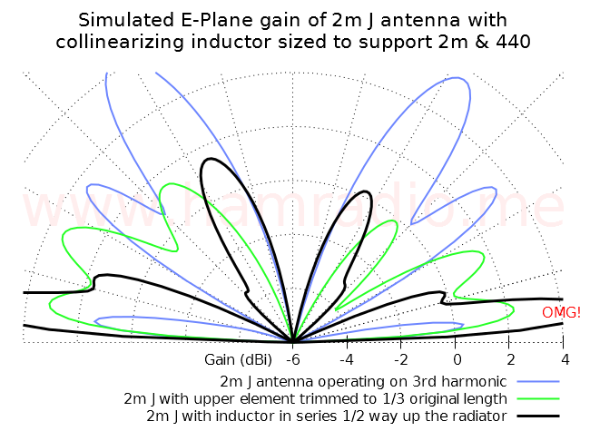
Hey now!! What a difference for the gain at the 3rd harmonic. Let’s readjust the graph to see where the gain peaks.
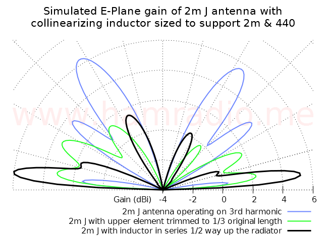
Nice. As usual there is a bit of gain advantage towards the J side, but wow. The new motto for these dual-band J antennas should be…
“if you can’t beat rf current, make it work for you.”
Patterns for the fundamental (2m) and 3rd harmonic (70cm)
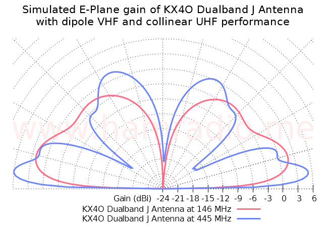
What about the gain pattern for the fundamental frequency? Figure 19 compares the patterns.
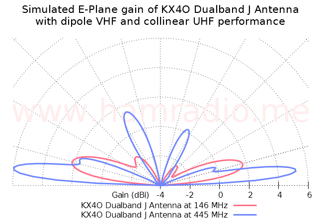
Now let’s return the overall gain range to something more familiar and compare with previous data from figure 4.
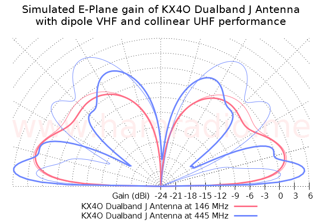
Figure 20 compares the improved dual-band J antenna (thick lines) with the previous regular J (thin lines). At 2m, not much changes although the slightly shorter main radiator does reduce the gain ever so slightly. 445 MHz is a tremendous improvement with using the entire radiator rather than choke it to just a single halfwave.
If this looks familiar… it should
This method of dualbanding a radiator exists aplenty in the 2m/440 mobile antenna market. The end-fed Diamond mobile on my Forester is pretty much the antenna above, but with a wound transformer in place of the J’s quarter-wave impedance converter. So really the above ideal solution isn’t anything new, but incorporating it into a J antenna design might be.
The KX4O dual-band J Antenna
No final design yet exists for this much improved variation on the J antenna. It is ripe for optimization with some final tweaks to the wire lengths, inductance value and feedpoint placement. Some modeling and prototyping should produce a rollup J that beats the pants off all others in figure 2 without compromising the fundamental operation.
Assuming a rollup J along the lines of Nelson Antennas can incorporate the inductor in place of the SlimJIM topology, a new high water mark of performance per unit size (rolled up) is in our future.
What’s in your pocket?


The big light went on when I read this. I'm understanding decoupling stubs better…. my first try worked GREAT!
same here