This previous post in this series gave some history concerning the classic “UHF” connector also known as the PL-259 and SO-239. As we continue the research into the “real” performance of the PL-259 and SO-239, we come to this post where the test configuration and the items under test are revealed.
Great laboratory equipment was used in this test, but some good amateur grade equipment is available for much less price and can verify some of the findings here. As you will read below the S11 measurement is really a form of SWR reading with a one port instrument. Check out Array Solutions for some possible choices in gear. The S21 measurement will be more difficult to accomplish with amateur level gear; However, used equipment may be available. I tested to 500 MHz, but the issues with the UHF (PL-259) connector system becomes apparent at around 70 MHz.
The Two Tests
There are two individual tests in this experiment: S11 Return Loss and S21 Attenuation.
S11 Test
S11 is analogous to the familiar SWR check, but with a bit more information. Return Loss measures how much energy is bounced back from the load to critique how well it absorbs power from the source – the more negative number in dB the better. For the most part, SWR and Return Loss can be calculated from each other. For completeness, I will show both SWR and Return Loss plots for the S11 test.
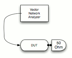
Figure 1 shows the simple connections involving one cable to the VNA and a 50 ohm terminator load on the other side of the device under test (DUT).
S21 Test
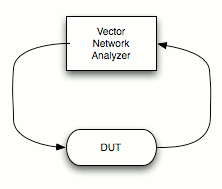
S21 is simply how much power makes it through the device under test. Losses are revealed in dB increments. Figure 2 shows the extra cable for measurement of the power through the device under test.
Frequency Test Range
Both the above tests will be performed from about 70 MHz (the point where losses began to appear) to 500 MHz.
The VNA
A good Vector Network Analyzer (VNA) calibrates the test cables as close to the DUT as possible and the one used for this is no exception. It’s good… trust me.
Note the VNA’s test cables have SMA connectors at the ends. Where needed, adapters are used to convert from SMA to the DUT. Sometimes, this means multiple conversions occur. Such is the case for testing the PL-259 and SO-239 as shown below.
Comparative Connectors
When critiquing any component it is always a good idea to compare it with other types of devices in its class. For this test I include samples from SMA, BNC, N, TNC and, of course, the PL-259.
Contender #1 – The SMA Connector
Because the VNA’s connectors are already SMA, a simple SMA barrel was used. No picture is needed for describe this I think.
Contender #2 – The BNC Connector
Who hasn’t seen or used this connector over the years. This use to be the standard connector for HT antenna ports. It is still the connector of choice for QRP radios. Originally designed as a smaller bayonet version of the Neill connector (of N connector fame), the Bayonet Neill–Concelman (BNC) connector is wildly popular.
Figure 3 shows the conversion necessary to get a complete test setup. SMA is converted to BNC and then goes into a bulkhead silver plated BNC barrel. One side connects to one port of the VNA and the other side connects to either a load for S11 or the other port of the VNA for S21.
Contender #3 – The N Connector
With the exception where lots and lots of power are delivered to the load, the N connector (named for Paul Neill [1]) reigns as the supreme consumer grade RF connector of choice for amateurs and many professionals.
Figure 4 shows the same sequence of adapters to get to the N with two SMA to N converters. An N barrel about one inch in length completes the test set.
Contender #4 – The TNC Connector
It looks like a BNC and acts like a BNC. In fact it is identical to a BNC except for the bayonet. This is the Threaded Neill Connector or TNC. This is likely the least popular connector in this test. It is my standard connector for everything in my ham shack less than 1kW, but the reasoning is for another post.
Figure 5 shows the adapters for the TNC connector test. It is almost identical to the BNC configuration.
Contender #6 – The PL-259 with 1 inch SO-239 Barrel
I found several UHF barrels around the lab for testing and this is the shortest one.
Figure 6 shows the tortured path to get to the UHF barrel. I had to convert from SMA to TNC and then use a TNC to PL-259 adapter.
The UHF connector system presents a varying impedance to the signal that is dependent on frequency; This is the primary problem with this connector. The disturbance to the signal should be proportional to the length of the impedance deviation. To confirm this, differing lengths of the SO-239 barrel were used… and here is one…
Contender #7 – The PL-259 with 2 inch SO-239 Barrel
This is the same configuration as before substituting a 2″ barrel for the shorter version.
Contender #8 – The PL-259 with a T Connector
Just for fun, I tried the T connector shown on the previous post. The SO-239/SO-239 part is between the two barrels above. Of course the transmission line has the PL-259 stub sticking out. I did not take a picture of this configuration, but it is exactly like the previous two.
Intuition suggests the T portion should really mess with the transmissive properties – perhaps the most. We will see.
S11 Test Terminator
All the above configurations include the 50 ohm terminator on one side for all the S11 tests as shown in the TNC example in Figure 8.
Perform the Test
I calibrated the VNA and performed the S11 and S21 test to all the above configurations.
In the next post I will show the results starting with tests of the post World War 2 connector designs.
In the last post in this series, I compare the above with the UHF connectors.
References:


great work
Excellent research. Personally, I always been dissatisfied with the *HF connector. The comment from one reader: "Just chop it off?" Well, actually, yes. On equipment that has an SO-239 panel/bulkhead mounted connector, replace it with a 2 hole, 4 hole or bulkhead Type-N Female. For crimp-on SO-239, replace it with a crimp-on Type-N Female. In each case, they are the same size and performance, as clearly documented here, is far superior.
I've replaced every one of my *HF garbage with Type-N, except for my last 2 radios, on those, I used crimp-on SMA Female. And, YES, on NEW equipment. (Also, keep in mind, that the SO-239's used by radio manufacturers are bulk grade crap, NOT the expensive top-flight Amphenol ones. My Type-N are Amphenol.)
NMO mounts are available with Type-N Male. Larsen has it with dual-shield RG-58, or if you prefer LMR-200, Larsen offers that with an SMA Male. The insertion loss of an adapter is negligible.
To continue. I replaced my in-line crimp-on So-239's on my most recent units, two Kenwoods, a 2M/440 mobile and a 220 mobile, with crimp-on SMA females, as I already have Larsen NMO mounts with LMR-200 and male SMA's (which match the SMA female on my HT). The losses of SMA connectors, as documented by these articles, are (virtually) non-existent and SMA's can easily handle over 100 watts, more than enough for any mobile setup.
Even for HF, I don't use *HF connectors because they are not at all weather resistant, for my setup, I've replaced all of mine with Type-N. It was not a difficult decision, as I wanted one connector type for all of my cables, and Type-N was designed for service in outdoor spaces. Rather than deal with adapters, I chose to "fix" my equipment by installing the connectors the manufacturers (Kenwood and Icom) should have used. It has been well worth it. I never worry about finding adapters or issues concerning using unsuitable connectors outside.
If you are concerned about the manufacturer's warranty, wait the for the warranty to expire, then replace them. Most of my equipment was purchased on the secondary market, as I'm retired and new equipment is too expensive for my budget, and the warranty wasn't an issue. On my 2 mobiles, I waited 60 days for break-in failures and then replaced the So-239's with SMA's.
Since part of Amateur Radio is perfecting our craft and improving our skills and equipment (unlike commercial equipment, we are allowed to modify our equipment), I don't understand why hams are so wedded to a connector design that became obsolete almost 60 years ago, even for HF equipment. Type-N connectors were designed in the '50's to solve the inherent limitations of the *HF connector design. It's past time that we hams also move past this relic of the past.