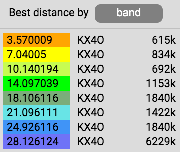
WSPR beacons heard by KX4O in Virginia
I got into the spotting game after playing around with some KiwiSDR receivers and WSPRDaemon on a Raspberry Pi 4. It didn’t take long to beef up the system to three KiwiSDR units. Two I dedicated to the task of monitoring the world of WSPR transmissions. Hooked to my 43 foot vertical antenna I have respectable results judging by the rank seen on the various database viewers. Click through the following for live data.


Key to this success was being ready for solar activity increasing activity on the higher bands. Fortunately my antenna choice and demodulation subsystems proved functional in this regard.
SDR spotting antenna
The 43 foot vertical, while not the best performing antenna on all bands, has shown to be admirable for receiving purposes. I have good coverage from LF to HF with a bit of noise below 250 kHz making 2200 meters a reach, but 630 no problem.
43 foot efficiency vs. frequency
The 43 foot’s lowest efficient frequency (1/4 wave monopole) is around 6 MHz. Below this, efficiency drops quick. This is clearly evident in the following spectrum from one of the connected KiwiSDR receivers. Ignoring the various live broadcasts, we are left examining the noise floor that is inversely proportional to frequency as seen between 7 and 22 MHz. Below 6 MHz to the top of the US AM broadcast band we see lower received noise floor due to antenna inefficiency. The noise floor above 22 MHz remains elusive when propagation doesn’t cooperate.
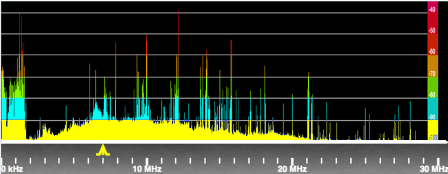
One requirement of this entire system for weak signal reception is to gain at least some access to the upper HF noise floor while not over driving the lower end.
When you’re trying to cover this much spectrum with one antenna system, you have to make some compromises. Mid to lower frequencies have more background noise than the upper end is relatively weak. It would be more lopsided without a pre-emphasis device I will cover later in this article. Note as well some signals are very strong such as the examples near 10 and 12 MHz highlighting a concern for saturating system components.
43 foot antenna results
That said, the spotting networks confirm WSPR reception across the bands.
The 43 foot antenna is it’s own topic with plenty of past articles to explore on this site. This antenna is 13 years old, but DX Engineering makes good stuff. Despite one bolt failure, the system has been fine. This particular version is the one with the 4:1 transformer at the base. It is fed into my house with about 240 feet of LMR-400 direct burial coaxial cable.
Repurposed antenna
It’s important to say this antenna was never meant to be part of some sort of WSPR spotting system. I originally used it for the usual amateur communications. While trying ground loops and other antenna techniques for a friend, I simply hooked this one up to the SDR system. It worked. This is a bit of a dull story, but sometimes things that happen in life just work out.
SDR spotting receivers
Two of the three KiwiSDRs are set to eight channel mode. These are connected to a copy of WSPRDaemon running on a single Raspberry Pi 4 computer. While the KiwiSDRs have the ability to decode WSPR transmissions, the actual demodulation occurs on the Raspberry Pi. WSPRDaemon is set to demodulate 12 bands: 630 to 10 meters. These twelve are divided six each to each KiwiSDR. The Ethernet traffic between these three devices is robust; I have dedicated Ethernet lines and a switch serving just this system.
Long story short, this collection works flawlessly with WSPRDaemon demodulating the audio snippets constantly derived from the Kiwis.
Site receive electronics
The antenna and SDR/WSPRDaemon subsystems are pretty much plug and play things that are ready to go for the user. It’s time to focus on the electronics needed to take the one antenna signal, tweak it, and split it to the multiple receivers. Let’s start with this diagram (click to enlarge)…

The coloring denotes three logical circuit groups:
- Passive pre-emphasis between antenna and first pre-amp (Blue),
- Broadband low-noise pre-amplification (red),
- No loss signal distribution system (amber).
Component specifics
Key features from left to right include…
- KX4O Implementation of the KA7OEI pre-emphasis circuit (FL1),
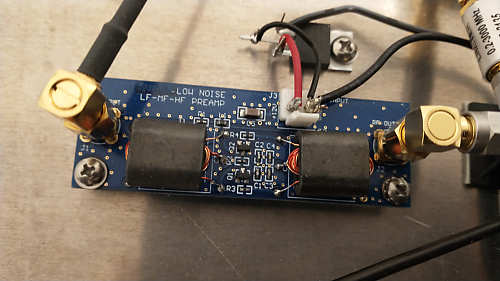
- LF-HF 15 dB J310 Preamp by SV1FAN (AR1) powered by a TO-220 12 volt regulator (U1) grounded and heatsinked to an aluminum panel,
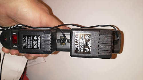
- TRIAD 15 volt linear power supply (PS1) with everything but the regulator,
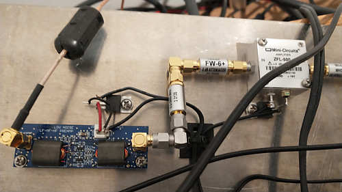
- Inline 13 dBm limiter (Z1) along with a 6 dB attenuator (AT1) to ensure the signal doesn’t exceed the input limits of the following gain block (AR2),
- 25 dB gain block (AR2) powered by a TO-220 15 volt regulator (U2) grounded and heatsinked to the aluminum panel,
- TRIAD 18 volt linear power supply (PS2) with everything but the regulator,
- Another 6 dB attenuator (AT2) to, more or less, make the overall gain of this entire system from antenna to one of the eight output ports dominated by the SV1AFN preamp (AR1),
- 1:8 splitter (A1).
Helps avoid common mode
One of the most repeated mantras coming from the WSPR spotting purists is the need to avoid common mode noise pickup. Well, you do what you can where convenient. This led to the selection of the TRIAD linear power supplies, with their transformer isolation, to power the two amplifiers. Of course capacitance coupling exists, but again… you do what’s convenient and move on… IMO.
Cost… and inflation
As of the date of this article, the above gear costs around $520… about 14% more than what I paid a year or so ago when I put all this together. If you’re interested in something like this, don’t delay purchasing the pieces… just sayin.
The pre-emphasis circuit
A key feature of this system, the FL1 pre-filter helps balance the gain response to LF, MF and HF noise. Clint, KA7OEI, makes these important points…
“HF noise power and signal level is (generally) inversely proportional to frequency. At lower frequencies – say, 2-8 MHz – the noise power is far higher than it typically is at around 20-30 MHz.”
“A direct-sampling SDR – or any receiver, for that matter – can tolerate only so much RF power on its front end. Traditionally, this is a mitigated with the use of narrow-band RF band-pass filters, but this can’t be done if one intends to be able to cover the amateur radio bands 160 through 10 meters (1.8-30 MHz).”
Clint tried various circuit configurations to lower the gain at the lower frequencies settling on this topology that re-purposes the familiar pre-emphasis concepts of yore…
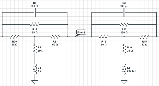
It does something like this…
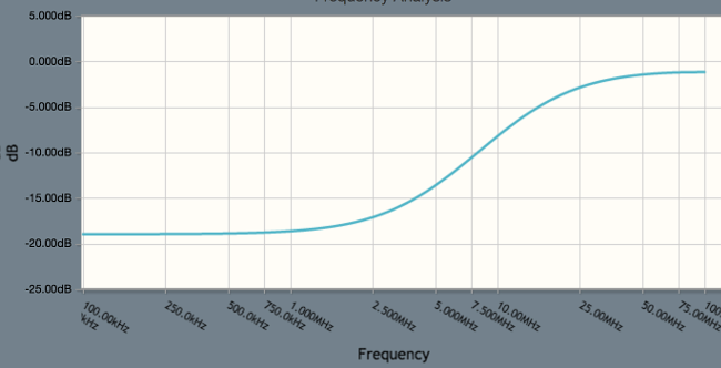
Applying the pre-emphasis circuit
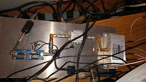
Here is a photo of the KX4O PCB that houses the circuit…
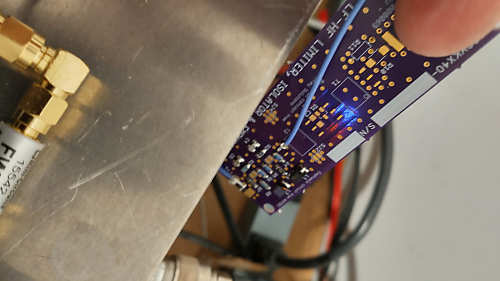
Yeah this is literally hanging off the side of the rest of the circuit with that little blue coax bypassing the unused limiter portion of the PCB. Whatever… it works for now. You can see the two stages of filtering at the bottom. Not seen is the connection to the antenna coax.
Figure 3 still shows lots of energy at lower frequencies, but at least the noise floor above 22 MHz is often measurable. Perhaps three stages of filtering might make sense, but given the success of the above two stage approach, I don’t really have some perfectionist urge to touch this anymore. Better is the enemy of good.
If I was a super purist, I would design filtering to consider the pass band of the 43 foot antenna as well as the frequency dependent noise it hears. I’m happy enough with my WSPR spotting ranking so… no.
Signal distribution
One could easily argue the need for the second level of amplification is questionable. Perhaps… and I did this on the first run with a 1:4 splitter. I could have simply piped the pre-amp directly into the 1:8 splitter and lived with less of the preamps gift of gain. However, attenuating the gain from the first low-noise amplifier seemed counterproductive and wasteful.
When I was formulating the circuit topology, I broke the task into two parts: pre-amplification and signal distribution. The latter took on a life of its own with the use of a Mini-Circuits amplifier that required some protection from high level signals… hence the need for the limiter Z1. The second amplifier’s purpose is to compensate for the loss through the 1:8 splitter… that’s all. The 25 dB gain was much more than needed to offset the 9 dB splitter loss. The addition of attenuator AT2, leaves an overall gain through the entire distribution section at 4 dB. A 1:16 splitter was originally planned and led the design, but the 1:8 was available sooner. Thus what was to be near 0 dB net gain turned into 4.
More pics
That block diagram makes all this look good, but pics tell the real story. With that in mind, and hopefully patience by the reader, please enjoy these pics.
Observations
- It works well enough to make one antenna service a bank of receivers from LF to HF.
- I occasionally see obvious mixing issues when a powerful shortwave station comes on the air with greater than -20 dBm hitting the SDR.
- The pre-emphasis circuit idea certainly is important for a broadband antenna approach.
- Maybe three stages of pre-emphasis would help tame the shortwave stations. I don’t think it will help with signal strength in the upper HF, but then again I don’t seem to have problems there once the bands opened.
- It’s likely a better plan to have dedicated band-specific antennas for smaller portions of the frequency range.
- WSPR spot results speak for themselves.
With eight outputs of LF-HF from one antenna, I feed three KiwiSDRs, one Heath WWV clock, one AirSpy HF+ feeding an OpenWebRX server (my everyday listening machine), a WWV experimental port. This leaves a few ports. I have a few more KiwiSDRs I may dedicate to FT4/8 spotting network soon.
Conclusion
I could probably wring more use out of one antenna, but am quite pleased with the result. This system is in a rural part of Virginia and that probably helps a lot with quality reception. One can’t always dwell on the reasons for success as sometimes it just falls together in a good way. Viva la luck.
