Tuning the small loop
Some have asked about the dc motor controller I put together for the small loop antenna project. I did look around for an off the shelf variable speed controller and found several. They were all quite expensive for what seemed like a relatively simple circuit. Given I spent $54 on the dc gear motor, I wasn’t keen on spending a couple hundred more just to vary a voltage. There had to be a better way.
Circuit design opportunity
A former analog circuit designer, I welcomed the opportunity to try my hand at dc motor controller design. It’s easy enough to design a variable voltage regulator, but can we add features not found in any commercial product? Perhaps, but before I wandered off in the weeds I focused on requirements.
DC motor controller requirements
Let’s list them…
- Operate a 12 volt dc motor on a small loop antenna;
- Power source 12-16 Vdc;
- Actuate the motor clockwise or counterclockwise;
- Be able to drive the motor at full speed (quick antenna frequency changes);
- Be able to drive the motor at very slow speeds (fine tuning antenna frequency);
- Provide a single rotating control with a center-off position;
- Not produce interference to a radio receiver;
After some development I would up with something that looks like this…
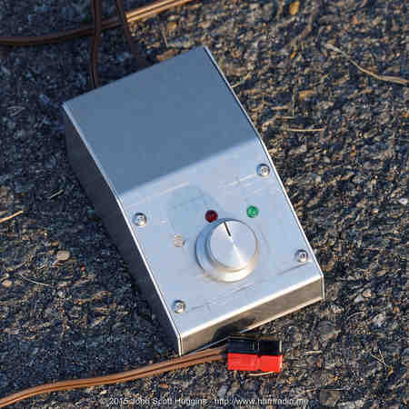
It’s not much to look at yet provides one touch control of a dc motor. If you like to twist knobs on your radio, this controller is for you. Let’s review some key features before going into the detailed design.
A micro-controller?
I thought very seriously about accomplishing the variable speed requirements with a straight analog circuit, but then I woke up and remembered this is the 21st century. As I will show, a whole lot of convenience and possibilities are available to a designer simply by popping a micro-controller into the circuit.
PICAXE 08M2
These days there are numerous options in the micro-controller trade space. Fortunately for us even the most mundane, simple and inexpensive micro-controllers add plenty of capability to designs. The PIC system and more specifically the PICAXE variant have solved a few problems for me in the past. The 8 pin PICAXE-08M2, complete with an A/D, 128 bytes of RAM, builtin BASIC interpreter, and a few IO pins is an incredible value at $2-$4.
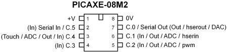
The builtin PWM generator provides the opportunity to easily use efficient switch-mode motor speed control. The PICAXE easily got the nod for this project.
The National LMD18201 (now a TI product)
Where’s the beef? It’s right here man. If you are like me, life’s too short to waste time making motor control circuits that just barely handle the task. Live a little and read on.
The convenient LMD18201 3-Amp, 55 Volt, H bridge IC Motion/Motor Control device is a well heat-sinked drop-in solution for driving a dc motor. This device includes extra internal logic that makes interfacing digital command lines straightforward. As well, the LMD182xx series of devices include thermal shutdown, proper H bridge timing and many more safety features. The one drawback is the $7-$17 cost. All said, you get a lot for your money and may well be a better value than a solution with discrete transistors. It’s perfect for driving the dc gear motor on a small loop antenna.
Another very important feature in the LMD182xx line is some measure of ESD protection. From the datasheet…
“These devices have limited built-in ESD protection. The leads should be shorted together or the device placed in conductive foam during storage or handling to prevent electrostatic damage to the MOS gates.”
Ever blown a FET? I have and with just static electricity. FETs are notorious for total failure when ESD punches through their thin gate-source barrier. Prudent circuit design adds a measure of ESD protection to any FET device. It’s nice the LMD182xx series includes at least some measure of protection out of the box. This part is ready made to slug it out in the real world.
This part use to be made by National Semiconductor that, I think, was purchased by TI. I have wanted to use this part in a design for over 20 years and now I finally did. I’m thankful the part has withstood the test of time and is still in production. This long availability says something about the utility of the LMD182xx series of motor control integrated circuits.
One thing to keep in mind about the LMD182xx line is the relatively high 0.33 ohm Rds of the internal FETs. You can obtain discrete FETs with much lower on resistance if you need to drive high power loads. For small motor tasks, the 0.33 ohm is not going to be much of a problem, but deserves a good hard look in your thermal design to be sure.
DC Motor Controller Schematic Design
This design marries the flexibility of the PICAXE micro-controller with the brutish LMD18201 motor driver IC. Click the picture below to open a PDF of the dc motor controller schematic diagram…
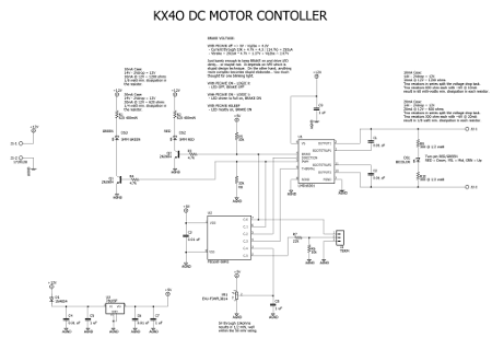
In addition to the PICAXE and LMD18201 integrated circuits you will find a voltage regulator, three LED indicators and some bypass passives. I was able to squeeze three LED functions into this design without going to a larger pin count PICAXE micro-controller:
- Brake Red LED – Tells if the brake mode is enabled in the LMD18201;
- Moving Green LED – Indicates if the motor controller is actively managing the motor;
- Direction two-color LED – Indicates by color which direction the motor is turning and how fast;
- All LEDs off – Sleep mode with motor drive off eliminating RF hash in radio receivers.
It is far more practical to simply up the pin count of the PICAXE and not try to tie LEDs directly to the actual LMD18201 signals and output, but something within me kept the desire for the 8 pin PICAXE.
Testing confirms the LEDs do perform their functions quite well although the color balance of the bi-color LED is a bit off especially during the 50% PWM stationary mode. Red and Green should make yellow, but it doesn’t quite work out that way in this circuit design due to the differing efficiency of each color’s LED. A solution is to add some diodes to the bi-color LED sub-circuit so different series resistors activate depending on the polarity of the PWM signal. This will provide independent adjustment of each color to achieve the desired balance at the 50% mark. This dances on the edge of stupid elaborate, but is a viable solution. Perhaps in the next board revision.
You might be wondering… when did a PWM value of 50% become the motor’s “off” state?
50% PWM = stationary mode
There are two ways to use the LMD18201 IC: “Sign/Magnitude” and “Simple, locked anti-phase PWM.” I choose the later. The explanation on page 8 of the LMD18201 datasheet describes it best…
“Simple, locked anti-phase PWM consists of a single, variable duty-cycle signal in which is encoded both direction and amplitude information [. . .]. A 50% duty-cycle PWM signal represents zero drive, since the net value of voltage (integrated over one period) delivered to the load is zero. For the LMD18201, the PWM signal drives the direction input (pin 3) and the PWM input (pin 5) is tied to logic high.”
It seemed easier to generate a PWM signal from the PICAXE centered at 50% duty cycle so I went with it. For all practical purposes this means I can control the motor’s entire speed range with just one PWM signal… so I did.
Circuit Board
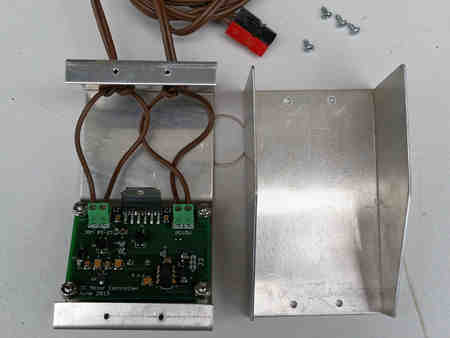
I made a PCB layout of the above schematic. This board mounts behind the control panel.
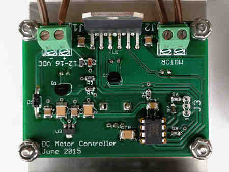
Note the beefy LMD18201 is along the top edge of the board ready to mount to a heatsink should the need arise… it hasn’t thus far. Two terminal blocks make for stout and reliable connections for power and motor connections. The 8 pin PICAXE is on the lower right while the voltage regulator sits on the lower left. The LEDs and control potentiometer are on the opposite side of the board and stick up through the control panel. J3 makes it possible to program the PICAXE in place.
The LMD18201 expects a certain amount of copper area on the power input pin to properly handle max power conditions. However unlikely this condition may be while operating the small loop antenna capacitor motor, designing in the proper amount of thermal copper area is something you only have to do once in a design.
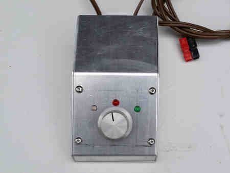
DC motor controller case
The entire circuit is housed in a small aluminum slant-front case to provide a nice angle for the control interface.
Here is the final assembly showing the center-detent potentiometer twisted slightly to the left, direction LED on the left, Brake LED in the middle and the Active LED on the right.
PICAXE code
As I wrote the code for the PICAXE micro-controller, I kept thinking of more and more features to stuff into it. A short list includes:
- Put the micro-controller to sleep after the front panel control is moved to its center-off position for a time to ensure the switching noise doesn’t interfere with radio reception;
- Change the speed in small steps near the center-off position and increase the speed changes the further away from the center-off position;
- Have a small band around the center-off position where PWM = 50% (motor doesn’t move);
- Have a small band near the CW and CCW control positions where the PWM is 0% or 100% for full motor speed;
Click here for Motor Controller PICAXE Source Code
The source code includes a state machine to manage the various stages of the motion control process including the all important “turn off” so we don’t have switching noise in our headphones. The PROM space is handy for a lookup table that performs the translation of the potentiometer position (via the ADC input) to PWM output. I used a spreadsheet to tryout different options and came up with the parabola inspired curve below.
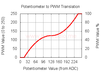
The left y-axis shows the number value sent to the PWM generator function in the PICAXE; By the way, the PWM generator is set to cycle at 2 kHz. The right y-axis indicates the resulting PWM value in percent. The x-axis is the 8 bit ADC value from the front-panel potentiometer wiper arm.
128 on the x-axis represents the center-detent position of the front panel potentiometer. Note how front panel control angular adjustments yield very slight changes to the PWM value and increase the changes as the knob swings towards the end finally resulting in full power at the ends. This is akin, sort of, to the velocity settings on your computer mouse where slow movements have fine resolution and quick movements trade resolution for high speed.
It is perfectly feasible and fine to use mathematics to calculate the motor speed based on the value from the potentiometer. This makes sense if all you need is a straight linear relationship between the two. If the relationship involves quadratics with some flat spots, such as my hybrid parabolic curve in figure 7, a simple lookup table makes a lot of sense and uses practically zero processing power. I’m not advocating either way as better or worse… the lookup approach simply solved the problem at hand first. If you desire to put sophisticated motion control math into your PICAXE I say go for it. Viva la choice.
I think it is fair to state this level of custom control over control-to-action behavior would be difficult, improbable or darn near impossible to accomplish in an analog only circuit… and all this for the cost of a Starbucks coffee.
Result
What can I say… It works. My favorite feature is the automatic sleep mode which tames any noise generation after a tuning session. This proves to be a critical feature since the way I’m using the LMD18201 always generates a 50% square wave to hold the motor stationary. With the sleep feature I can have this mode only when I need it, and have the circuit turn off automatically when I don’t. This mostly fulfills the requirement to avoid generating interference by turning off after a tune.
By the way, the noise is a useful feature during tuning if you have a spectral display and narrow-band antenna like a small loop – you literally watch the noise-peak move on the display while tuning. Pretty cool.
I’m glad to have made a PCB board for this design to include a stout ground plane. Marrying digital electronics with power circuits often creates problems. Thus far, I’ve not seen the PICAXE react in any negative way to the LMD18201 manhandling the dc motor currents. The two layer PCB is likely the reason… I certainly would not want to try this with perfboards or other less robust methods.
I have a Power Pole connector on the motor controller power cord and about 40 feet of lamp cord running to my small loop antenna. So far so good.
The screw terminals are a big win in this design. They hold the power and motor wires securely.
Other uses
The above circuit was designed entirely for controlling a small loop antenna’s tuning capacitor like the one I built for 30 and 40 meters. Other potential uses include:
- Remote tuning control for a big HF monopole;
- Variable speed control for a home-brew light duty antenna rotator;
- Variable speed control for a telescope declination axis;
- Control for a telescope filter wheel system.
There are lots of dc motor applications where this relatively simple circuit can fit in. The reprogrammability of the PICAXE opens up many possibilities to completely change the behavior through firmware changes.
Future Revisions
No design is perfect and this one is no exception. Despite the success in using this controller for the small loop antenna project, some day I may revise the circuit board design with these changes:
- Add circuitry to balance the red and green intensity in the bi-color LED (I really want a nice bright yellow at 50%);
- Add ESD protection across the power supply and motor PCB connections to augment the motor controller’s builtin protection and provide some protection for the PICAXE and voltage regulator (cheap insurance);
- Rearrange the LEDs to provide a better “look” on the control side (the knob I used was much larger than I originally intended);
- Add some weight, friction or something to make the control knob a little less easy to spin – it’s has a lightweight cheap feel;
- Surface mount the NPN transistors;