Small loops, growing popularity
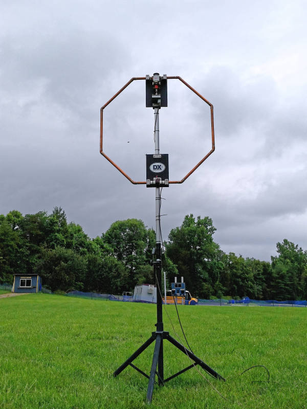
Small Loop HF antennas, often called magnetic antennas, seem to be all the rage these days. I suppose this old concept offers hope to folks in the ever tightening constraints of shrinking antenna space. I decided to follow on the ham-sexy mobile small loop antenna with this version meant for portable operation.
Whereas the mobile small loop HF antenna used 1 inch copper pipe in a great big rectangle, I used 3/4 inch for this example to allow use of the popular 2.4 inch diameter toroid as a ferrite-core transformer feed. The scrappy prototype didn’t work well during its first field trial during the Virginia QSO Party, but this later refinement made a successful debut in June during Field Day 2015.
Topics in this article include:
- The radiating “loop” element
- High voltage capacitor tuning sub-assembly
- Capacitor location: where is it actually?
- Tuning motor sub-assembly
- Small loop toroid feed transformer
- Motor cable RF choke
- Small loop antenna mast mount system
- Conductive mast – seems okay
- Small loop antenna – tuning gymnastics
- Motor Controller: Built-in noise source
- Small loop antenna drift
- Frequency stability good enough
- Useability
- Efficiency
- Fields – strong ones
- Conclusion
The radiating “loop” element
Let’s examine the octagon…
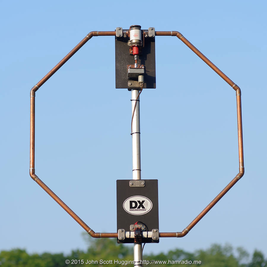
What you see here is one continuous copper octagon broken at the top to facilitate attachment of the high voltage tuning capacitor. Anyone familiar with copper plumbing pipe realizes the ready availability of parts to make this octagon using the 45 degree corner pieces. The bottom of the octagon is not broken, but surrounded by the little toroid feed transformer. The DX sticker came from an accumulating pile from several DX Engineering orders. “As this assembly uses lots of DXE parts, why not put their sticker on it” I thought. Please understand this assembly is NOT a DX Engineering product and in fact many of their off-the-shelf components require modification to accommodate the copper pipe diameter. That said, the parts from DXE sure make it easy to design sturdy antenna assemblies.
High voltage capacitor tuning sub-assembly
Let’s examine the tuning portion of the antenna…
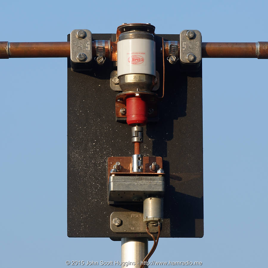
That’s the same Comet 5-500 pF, 5000 volt capacitor used in the HF small loop mobile antenna. That thing was just sitting in the garage so the capacitor was re-purposed for this project. Below the capacitor is a DC gear motor; I chose the highest ratio, slowest RPM from the many choices. Between the variable capacitor and the gear motor is an insulating shaft and offset coupler to allow for some assembly slop of the two rotating axes. The top of the copper octagon is clamped to a black plastic rectangle plate which is, by the way, the same item as used in the AHVD Antenna and is available pre-drilled for the AHVD from DX Engineering. The holes in this plate facilitate mounting to the vertical mast and mounting the two clamps holding the top of the copper octagon. Additional holes were drilled to accommodate the motor and capacitor brackets.
The capacitor is suspended on custom copper straps cut and shaped to provide:
- suspension of the capacitor,
- electrical connection between capacitor terminals and the copper octagon,
- firm mounting to the black plastic plate.
The copper pipe mounting points use the DX Engineering 3/4 inch Resin Support Clamps with custom machining to accommodate the 7/8 inch OD of the “3/4 inch” copper pipe.
All the above is affixed to a vertical aluminum mast just like the AHVD Antenna.
Here is a closeup of the capacitor…
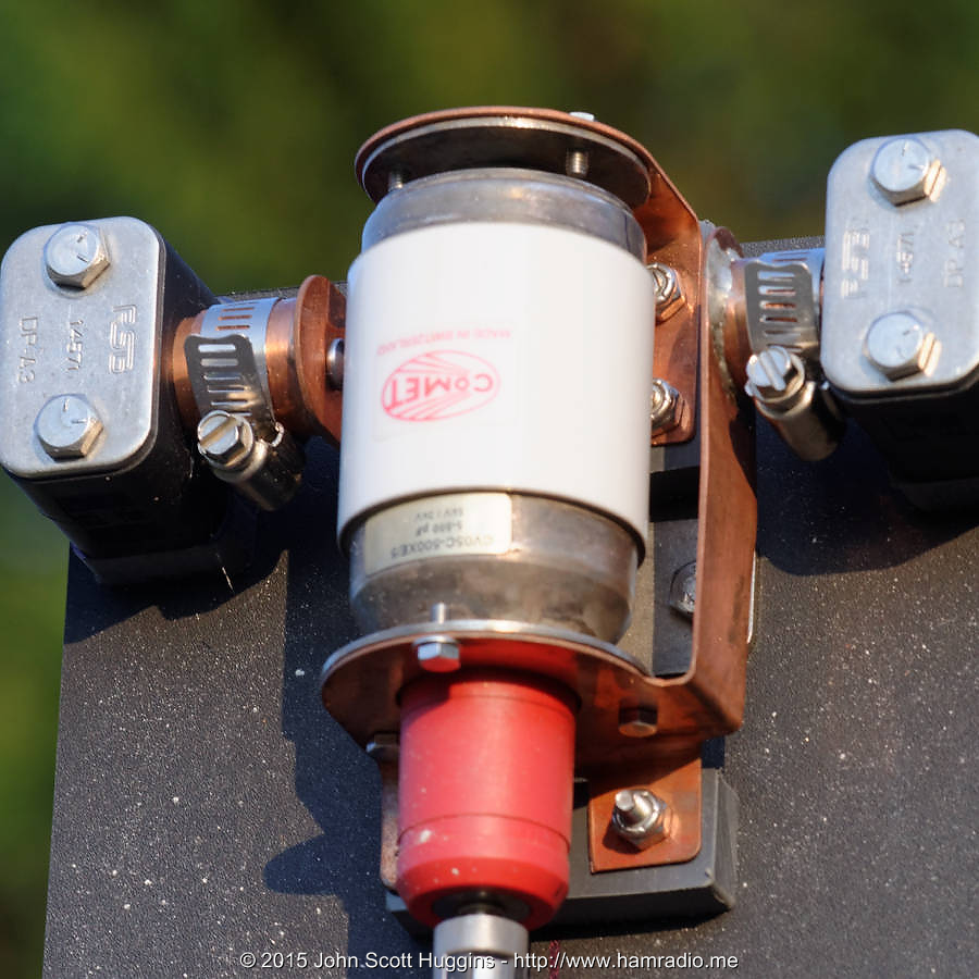
You can more clearly see the bent copper pieces surrounding and mounting the vacuum capacitor. The two hose clamps are the only points along the pipe path where the electrical connection is not soldered. Two pipe end caps are soldered to the tabs of the straps. The caps have slits added to allow the clamps to compress against the pipe. The other end of the straps clamp to the capacitor round flatplate terminals via two sets of three screws. The copper straps attach to the plastic plate above non-conductive spacers. These are for mechanical mounting only. The resistance of all these connection boundaries were my biggest worry, but the measured performance suggests the resistance is low enough to not be a bigger factor than design expectations.
Capacitor location: where is it actually?
Some of you might be asking the question…
Hmm… just where is the actual capacitor ‘center’ along all those twists and turns?
Great question. Another is…
Where is the center of capacitance in the capacitor itself?
The answer to both in my mind during construction was “I don’t know” as I focused mostly on mechanical assembly than electrical realities. I thought long and hard about protruding the capacitor above the plastic plate to better center it to the axis of the copper pipe. In the end, I decided to not expose this costly capacitor to more mechanical exposure than absolutely necessary. It seems I paid a small price. This next figure highlights where I found the low voltage point directly opposite the real capacitance point…
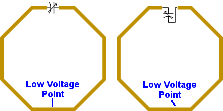
The asymmetry of the tuning capacitor and its copper straps moves the location of the low voltage point just a bit. I could easily test this by moving my finger along the copper pipe while observing a network analyzer. The low voltage point does a very good job of showing no interaction whatsoever with the tuning and behavior of the antenna just like in a typical dipole antenna. The “touch test” reveals high immunity to external dielectric influences at just this point. Ideally the feed transformer should be at this location. It isn’t. Oh well… it’s close enough to not have appreciable detriment to the antenna’s performance. This asymmetry bugs me quite a bit, but as they say “better is the enemy of good enough.” I also wonder how well the capacitor maintains the capacitance “center” along its 5-500 pF adjustment range. A test for another day.
I believe one reason I got away with mounting the feed capacitor not quite on the low voltage point include:
- The transformer is 100% electrically isolated from the copper tubing… at least at DC;
- Theoretically the transformer should drive a current almost anywhere along the loop since small loop antennas, by definition, have nearly constant current around their entire circumference.
Voltage, of course, increases briskly as you move away from the low voltage point culminating in hundreds if not thousands of volts across the capacitor; The AA5TB loop-calculator-spreadsheet suggests just 10 watts at 40m places over 1200 volts across the capacitor and about 3,000 volts at 100 watts! I think I’ve made a reasonable case you can get away with not being spot on the low voltage point for your feed, but DO NOT take this as gospel to just slap the feed anywhere it fits. It’s likely prudent to find and get as close to the low voltage point as practical with whatever mechanical adjustments are possible. I seriously thought about mounting the transformer just outside the lower right pipe mount, but just couldn’t make the antenna that odd looking. I mean really at some level custom antenna projects are artistic expressions. Would folks view the Mona Lisa differently if Leonardo portrayed her eyes asymmetrically?
Tuning motor sub-assembly
Here is the $54, 12 volt, 0.6 rpm, DC gearmotor from McMasterCarr…
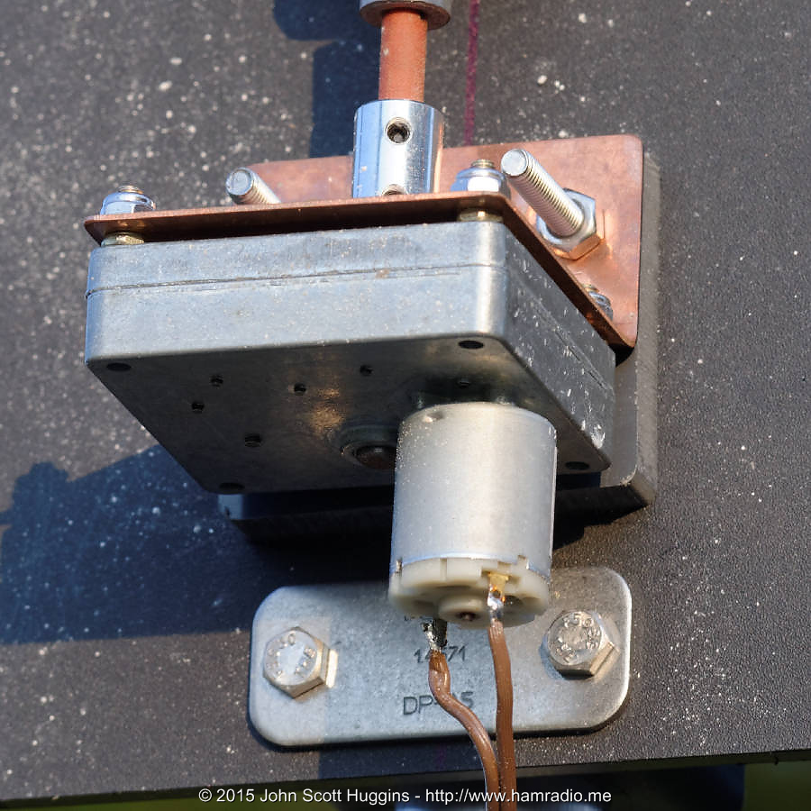
This particular gear motor product is available in a variety of gear ratios in the same mechanical footprint. This gives the designer some flexibility later if the initial guess at gear ratio is not optimal. The copper angle holds the motor to the black back plate. It should have been aluminum, but this does look cool.
Beware: Motor shaft is not on motor housing center-line
If you use a gear motor in your projects pay close attention to the dimensions of the casing with respect to the position of the output shaft. My motor’s shaft is asymmetrical to the mounting hardware positions. This is highly annoying as it is almost on a center-line, but not close enough to prevent a serious bend in the shaft coupler if you don’t account for it. I didn’t notice it until I loaded the convenient STEP file (provided by McMaster-Carr) into my CAD model for this whole assembly. After some disbelieving stares at the model when joining the components along the drive train, I finally noticed the motor mount points offset a bit. The whole motor assembly is shifted slightly to the right to place the shaft on the center-line of the mounting plate. All hail 3d CAD modeling.
Small loop toroid feed transformer
Moving down the antenna we arrive at the bottom black plate and the feedpoint…
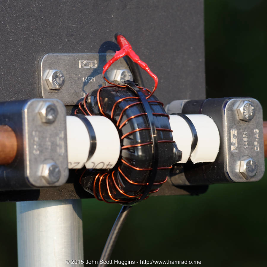
Of the many ways to feed a small loop antenna, this step-down transformer seemed the most logical approach given we are attempting to match 50 ohm transmission line to an antenna impedance measured in dozens of milliohms. This particular transformer is two Type 43 2.4 inch diameter toroids stacked together, taped and then wrapped with as many turns of wire I could reasonably fit. The math suggests the turns ratio should be higher, but you do what you can.
The toroid transformer easily slides over the 7/8 inch OD (3/4 inch standard size) copper pipe including the layers of electrical tape wrapped around the pipe to electrically isolate it from the winding. This toroid assembly will pass around the 45 degree bends as well providing a way to remove it from the soldered loop when disassembled from the plates. To protect the transformer from slapping around and shattering, two white PVC halves center the transformer between the DX Engineering resin support blocks. The red stuff is liquid electrical tape applied many times to weather seal the connection to the coaxial cable leads.
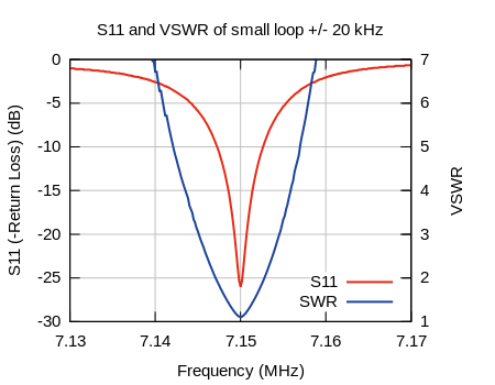
The selection of Type 43 toroid material, wire size, number of windings, etc. were an educated guess. My primary purpose for this particular small loop antenna is the 40m band. I got lucky. Lo and behold it tunes up quite well at 40 – 30m. Here is the, quite narrow, S11 with respect to the entire 40m band with the antenna tuned to 7.15 MHz…
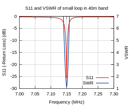
Yes, very narrow. This view of the small loop bandwidth in the entire 40m band gives you an idea where this antenna might be helpful performing the role of pre-selector filter at, say, Field Day.
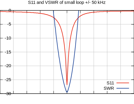
Let’s zoom in to 40 kHz width…
With the broad range of the vacuum variable capacitor, this antenna does show resonance at 80m, 30m, 20m and 17m and more, but not good enough for me to bother using it on these bands except maybe 30m. 80m is very inefficient and the high bands are likely out of the optimal range of my toroid transformer. The broadband experience of other small loop builders with the traditional smaller loop within the main loop feed suggests my transformer’s characteristics are the limiting factor. More experimentation is in order.
Motor cable RF choke
Let’s now move down to just below the feedpoint…

The lengthy DC motor control cable affects the performance of this antenna. This simple choke cures this problem. Note the aluminum mast doesn’t seem to affect the antenna despite the small loop’s vertical polarization… more on this below.
While the DC gear motor is relatively cheap at just over $50, the off the shelf motor control cost is in the hundreds. I made my own with an $18 LMD18201 motor controller IC, center-detent potentiometer, 8 pin PicAxe microcontroller and a few status LEDs. Here it is all tucked away in a table top box…
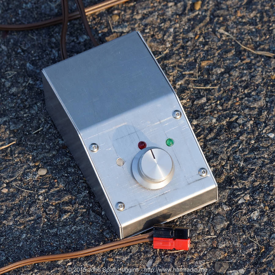
This box has just two cables: DC power and DC motor. Both connect directly to wire terminals on a custom circuit board. The free end of the DC power-cable has a standard Powerpole connector that has quickly become my standard power connector for everything. You get a lot for your money with the LMD18201 component. The LMD18201 is configured in the “Locked anti-phase PWM” mode where zero motor speed is when the duty cycle is 50%. Twist the pot left or right and the duty cycle decreases or increases to vary the speed. To save power, when the PicAxe detects the pot is near midrange, it shuts off the PWM signal entirely putting it effectively to sleep. This is good because you can definitely hear this thing in the radio when active. I have the PWM frequency set to 2 kHz. Yes the motor vibrates and makes sound during operation.
Small loop antenna mast mount system
The last picture is the other side of the loop showing how the AHVD plates firmly hold the loop to the vertical mast at four points…

Did I say firmly? Yes I did. This assembly is rock solid. Overkill? Depends on your point of view I guess. The DX Engineering components provide a very secure system for many antenna projects. Their focus is aluminum tubing, but their resin support blocks are relatively easy to modify to work with copper pipe outside diameters.
Conductive mast – seems okay
I thought long and hard about that aluminum conductive mast. Most small loop antenna builders use nonconducting materials in their support structures. Indeed I considered using a fiberglass 1.5 inch diameter mast. One thing kept me thinking this wasn’t necessary. Though other folks’ loop builds avoid the conductive mast, they often have a conductive coaxial feedline or motor control cable stretching across the loop from bottom to top. If this is the case, what difference would a conductive mast make?
I put the loop into simulation with and without a nearby vertical mast. Despite the vertical polarization of the antenna, the mast has no appreciable effect. I didn’t simulate longer masts for the time being, but I suspect if the mast length approaches 40m resonance, the results may be different.
Experiments reveal the DC motor control cable did have a noticeable effect on the antenna operation. Adding the choke to this cable mitigates the issue.
The small loop antenna feedline seems to have no perceivable effect on antenna operation apparently not needing additional common mode abatement. I remain skeptical of my own observations, but so far so good.
Small loop antenna – tuning gymnastics
Tuning small loop antennas isn’t the easiest thing to do. One particular hammy item that really helps is a spectral display. I use an Elecraft PX3 and sure enough, the small loop antenna’s narrow bandwidth makes spotting its current frequency relatively easy if it is within the bandwidth of the display. Here is a 100 kHz wide screenshot of the PX3 with the antenna tuned to 7.150 MHz below a 100 kHz wide S11/SWR graph so you can directly compare the two.
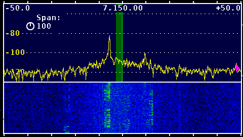
It’s not very obvious, but if you look close you can definitely see a bulge in the PX3 spectral display around 7150. This correlates well with the measured S11, but notice the reception range is a bit wider than what we could call a well tuned antenna. Nothing really new about that right? I guess you can say this antenna serves the role of pre-selector to some degree. Note the several LSB chats occurring on top of the always present noise.
The vertical green stripe in the PX3 display reveals the LSB demodulation bandwidth. You quickly see why moving the antenna frequency down just a bit ensures all the demodulation bandwidth rests within the antenna passband. The current settings above will likely work as is, but why not get everything you paid for in antenna and radio. Tweak it man.
Motor Controller: Built-in noise source
Not shown, but certainly interesting is the fact the DC motor control generates quite a bit of hash on the band especially in slow mode. This hash increases the noise and makes the bulge even more evident during tuning. I don’t think this hash has enough radiating power to worry about, but will need to check – I sure don’t want an OO notice! This may be one of those rare moments when an unintended consequence (PWM motor hash noise) becomes a broadband noise tuning aid.
Small loop antenna drift
I noticed sunlight reduced the frequency a bit as the small loop antenna assembly became warm. Here is a comparison of the before and after center frequencies after about 30 minutes in the sun…

This is enough to worry about, but at least it is a slow change over time.
Frequency stability good enough
The frequency stability of this small loop antenna is remarkably stable in short timeframes. Other than the heating effect above, I have not witnessed much drift at all. I give a lot of credit to Comet for making a reasonably stable, super smooth vacuum variable capacitor and the gear motor for facilitating barely perceptible shaft movements during tuning.
Useability
Tuning for SSB – a new adventure
Tuning this thing is a squirrely new adventure for the rookie. This antenna’s bandwidth is just wide enough to contain the bandwidth for a SSB communication. It’s narrow enough you must think about tuning the antenna to the midpoint of your SSB channel. Your radio’s SWR measuring system will likely generate a tune signal on the carrier edge of the SSB channel so you need to think this through to get it right.
Tuning for CW and Digital – not so bad
It’s a lot easier to tune this near your digital or CW frequency. The bandwidth is broad enough to allow you to search and pounce for a while before adjustment is necessary.
Motor backlash – maddening until you get use to it
Even with the highest ratio gear motor fed by my variable speed controller, this thing still tunes pretty quick in the 40m band. If you overshoot and try to go backwards, there is a whole lot of slop that happens before the frequency begins moving the other way. You get use to it after a while. One technique to defeat the backlash is to run the motor the other direction full blast for a 1/4 second or so to get things all tight then move slowly. With some practice, I was able to do what I wanted during frequency changes. If you enjoy twisting knobs on your radio, you will enjoy this.
Efficiency – 5 to 6% at 40m?!?
Some NEC simulation analysis of the bandwidth of this assembly with perfectly conducting materials suggests the bandwidth is much much less that the measured values above. The feedpoint resistance of the loop with perfect conductors is about 20 milliohms. Only when one distributes about 140 milliohms around the loop does the bandwidth broaden to the measured value at 40m as Q drops. Add the 140 milliohms loss and we have about 160 milliohms feedpoint resistance of which most is due to ohmic loss. NEC reports 100% efficiency for the perfect conductor, but shows about 5% with the added loss. This roughly matches the efficiency reported by the AA5TB loop calculator spreadsheet. Underhill reasonably suggests this loss should result in measurable heat.[1] His experiments suggest loop efficiency may be higher. This warrants further investigation, but for now I am sticking with textbook expectations of an electrically small antenna such as the loop where 5%, while small, isn’t an unexpected value.
A separate calculation using Owen Duffy’s calculator shows just over 6% efficiency yielding an antenna gain around -10 dBi… 12 dB down from what’s possible.
Efficiency is in the mind of the beholder as G8HQP reminds us…
“That would depend on what you mean by ‘efficient.’ Probably not efficient in the usual engineering sense of power out vs. power in, but perhaps ‘efficient’ in the common meaning of being able to do the job of radiating something from a small space.”
12 dB loss is 12 dB loss… more than a little… less than a lot. You have to be the judge whether an electrically small antenna is worth the loss… about two s-units down in this copper octagon example.
Keep in mind the details above are a 40m example. The efficiency gets worse at longer wavelengths, but steadily climbs for shorter. A loop this size for 20m and up can have relatively decent efficiency all other things being equal.
Fields
Ever wonder what the electric and magnetic fields around an electrically small antenna might be? Stronger than one might think as the following figure reveals.
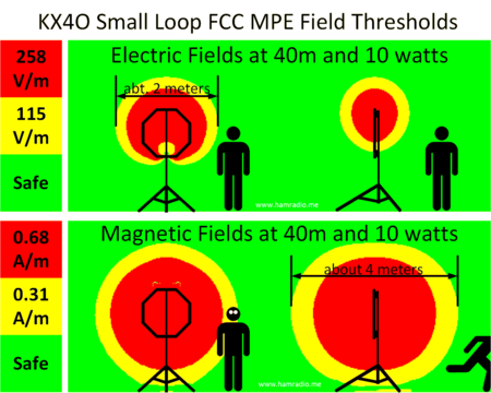
Red indicates levels beyond the FCC’s Maximum Permissible Exposure. Yellow indicates the threshold for the lower “general population” levels. Now of course there is more to “exposure” than meets the eye including time in fields, duty cycle, etc. Read all about it on the internet. Just keep in mind these small loop antennas are no shrinking violet when it comes to dominating the local environment with fields the FCC suggests are worrisome… and with just 10 watts power!
It’s worth noting a large fraction of folks experimenting with small loop antennas measure energy around their antenna with e-field meters, often spiffy home-brew examples, while ignoring the h-field entirely. As h-field meters are a bit more difficult to design and build, one can understand why this happens. However, they miss important considerations such as:
- If you are exploring the induction fields of an antenna to ascertain something about the far field pattern, one needs to examine both the e and h fields (and their phasing too really).
- Ignoring the h field can provide a false sense of safety security as the above figure attests.
Great big fields with far reach as revealed above are kind of a drag really. A key point of small loops is to put them places where full size antennas cannot go. Apartment dwellers are one example. I’ve seen a few pictures of operators snuggling up to their loop antenna during trail or park activations. Snuggling is likely ill advised. One should exercise caution and prudence when operating small loop antennas.
Conclusion
Well it works. I contacted 12 of 13 states in the 13 colonies special event during the Independence Day weekend all on 40m, using the loop and with ten watts. It did okay at Field Day 2015, but wasn’t what I might call a pileup breaker, but then again we were QRP using a small loop antenna. I’m quite satisfied with the mechanical robustness of this implementation, but then I tend to overdo antenna projects like this. The speaker stand remains my favorite tripod for almost everything including antennas.
Electrically small antennas are always compromises:
- Efficiency often takes a hit although some argue this isn’t as big a hit[1] as some think.
- Bandwidth shrinks markedly, but with some patience and sound construction, it seems manageable.
- About the only advantage of an electrically small antenna is the convenient size.
- A dipole will likely score big over this antenna, but you will need to get it up a bit.
- The vertical polarization of the small loop antenna arranged as shown above will at least suffer less ground loss than any horizontal antenna at the same height.
My biggest fear while building this small loop antenna is how well it will hold frequency once set. Despite the slow drift in the hot sun, the stability is plenty sufficient for typical use so long as you keep the motor controller reasonably handy at your operating position.
This antenna is a nice addition to the choices we have in our operating habits. If you desire a quick deploy 30-40m antenna that isn’t very high and just sits on the ground, this variation is an option for you. This design is useful enough to pass the fun test. I find I set this antenna up often to warrant keeping it around for a while.
References
- Small Loop Antenna Efficiency, Mike Underhill, 2006-2008


Nice job !
Author was determined to not be impressed because this is a SMALL antenna. Wonder if he is acquainted with the research done by K8NDS. Running QRP amid KW stations was the main issue in his effort.
I'm quite happy with it.
Did you give the dimensions of the loop. I got that the tube diameter is 22mm, but I could not find the loop edge size or equivalent…. Owen
I see now 3' diameter… is that the major diameter (between vertices through centre)?
Did you consider using a stepper motor instead? They can be RF-noisy while running, but they give you cheap, precise control over movements.