The CP22E High-Gain Mono-band Antenna
The assembly manual’s description describes the Diamond CP22E antenna best…
“The CP22E is a 2-meter monoband, 2-5/8 wavelength groundplane antenna, optimized for the U.S. amateur band. Made from heavy-duty aluminum, the CP22E is easily assembled, yielding excellent performance with 6.5 dB gain over a 1/2 wave dipole.”
Emphasis added on specifications that don’t stand up to analysis or Diamond’s own measurements. This one blemish doesn’t spoil the positive attributes. Let’s have a closer look at the CP22E to see why.
Sleek look
The Diamond CP22E maintains a slender look with relatively thin aluminum elements. Here is a view atop an 8 foot fiber glass pole and speaker stand.
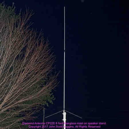
The next photo provides a sense of scale of the CP22E.

The CP22E in the portable configuration above provides a gain antenna well above the roof line of vehicles. Hence this combination is a perfect 2m vertical antenna for portable operations such as ridge busting horse endurance rides.
Mechanical design
The CP22E has thin, wind tolerant aluminum elements. The one on my roof has held up against 50 mph gusts thus far. The other CP22E I use for events took a tip over recently and sustained some damage.

The buttery aluminum used in the CP22E is adequate for wind handling only because it is so thin. It seems to do well in the winds, but take great care if using for portable purposes.
Electrical design
As Diamond’s description attests, the CP22E electrical design nurtures antenna currents similar to that of a properly spaced vertical collinear 2 bay antenna. Figure 3 showcases a simulation wire model of the CP22E.
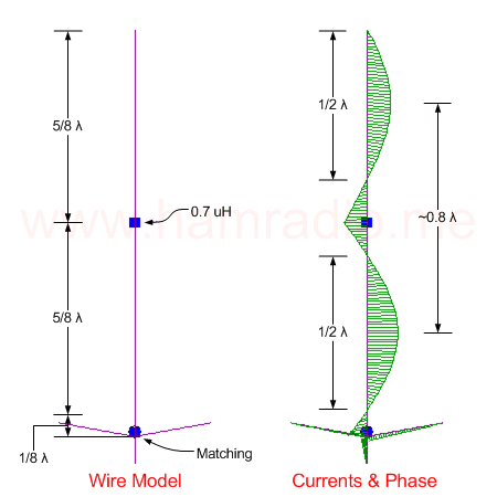
Key features include from top to bottom:
- Top element made of ~1/4 inch diameter aluminum tube with length approximately 5/8 wavelength at 146 MHz.
- Phasing coil ~1.5 inches in length with an approximate 0.7 uH value for properly phasing the upper and lower elements. Think of this inductor as “consuming” most of the middle half-wave of out of phase antenna current leaving only the upper and lower current peaks to radiate in phase.
- Lower element made of 1/2 inch diameter aluminum tube with length approximately 3/4 wavelength at 146 MHz. This length includes a 5/8 wavelength component along with an extra 1/8 wavelength section to give a matching section a better impedance to chew on.
- Matching section with the high-pass characteristics of a dc open circuit between the antenna RF connector center conductor and the antenna elements plus a short circuit between antenna elements and mount/coax shield. *
- WX resistant metal treatment on the two aluminum tube elements with an electrically insulating coating.
- Three decoupling radials of 20.25 inches in length.
The currents shown in the right side of figure 3 reveal how the designers successfully manipulate the phasing to produce two prominent in-phase current peaks with near ideal vertical separation to approach the theoretical max 3 dB of gain over a dipole antenna. Out of phase currents exist between and beneath the two current peaks, but are of small amplitude.
* If you perform this check yourself, know the aluminum tubing has a non-conductive metal treatment coating. Place your probe on the fixing screws instead.
Matching Section
The wild impedance present at the base of the aluminum tubes is nowhere near 50 ohms so the matching section provides the solution. Figure 4 shows the 4nec2 calculations to transform the strongly capacitive impedance (251-j297 ohms) to 50 ohms using low-pass and high-pass configurations.

The following clues reveal which solution Diamond Antenna uses for the CP22E.
- There is a dc short circuit between the vertical elements and mounting structure/feedline shield suggesting Xparallel is an inductor.
- There is a dc open circuit between the vertical elements and the feedline center conductor suggesting Xseries is a capacitor.
Hence the only viable choice is the high-pass circuit with a capacitance in series and shunt inductor on the vertical element “LOAD” side as shown above. A safe assumption is the 251 – j297 ohms impedance from simulation is likely a little different from the actual antenna. The point is this transform circuit with suitable values of Xs and Xp can bring it to 50 + j0 ohms.
CP22E VSWR and S11
Let’s compare the simulation values (with the above high-pass correction circuit) of VSWR and S11 with actual measured values. Note the measured values have a 12 foot piece of RG58 between antenna feedpoint and VNA.

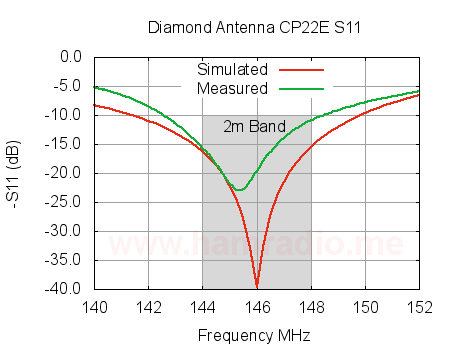
The measurements and simulations agree quite well suggesting the simulations are a reasonable portrayal of the CP22E performance. The Diamond CP22E covers the entire 2m band with ease.
CP22E antenna pattern in the E-plane
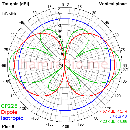
Figure 7 reveals the simulated 5 dBi gain pattern in the E-plane (vertical cut in free space) from the Diamond CP22E 2m antenna in green. For comparison an isotropic and dipole antenna are shown to provide a sense of pattern enhancement of the CP22E.
Diamond’s antenna pattern measurement
The Diamond web site contains what appears to be a measured antenna pattern of the CP22E. It states no absolute gain reference, but the markings do show -1 dB, -2 dB, -3 dB, etc. from the outer ring. This scale hint allows direct comparison between the simulation and Diamond data. Figure 8 compares the scaled above simulation pattern (red) superimposed over the Diamond antenna pattern (black).
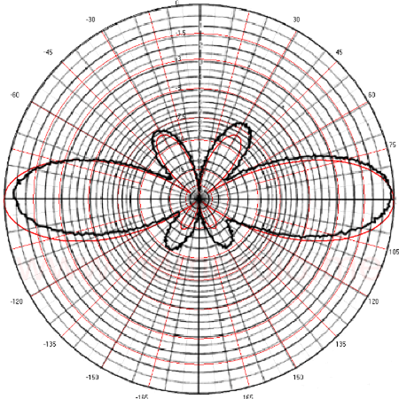
It’s easy to conclude the simulation results agree rather well with Diamond Antenna’s gain pattern further validating modeling accuracy.
Extended double Zepp
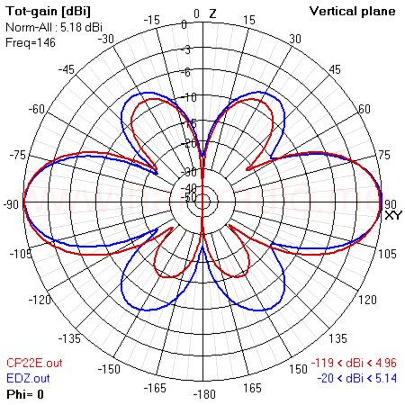
Does the CP22E antenna pattern jog your memory? If any of this looks familiar, you’re right. The current peaks so arranged along the length of the CP22E antenna are almost identical to what you achieve with the classic, center-fed Extended Double Zepp antenna. Figure 9 compares them both…

As well, the patterns of both in figure 10 are remarkably similar with both achieving directivity of about 5 dBi… almost, but not quite, 3 dB over a dipole antenna.
Diamond CP22E Gainflation
Notwithstanding the fact Diamond Antenna suggests this antenna has a gain of “6.5 dB” where dB without a point of reference is meaningless, one might argue they assume the gain reference from the very definition of gain itself… the isotropic radiator. With that assumption, the gain claim is still 1.5 dB more than the 5 dBi (~3 dB over a dipole) theoretically possible with two, collinear, in-phase current peaks. But wait, there’s so much more… let’s check their description statement again…

Ahh so now the gain claim rises to 6.5 dBd or about 8.7 dB over an isotropic. 8.7 dBi eh? As said above, the theoretical maximum gain improvement of two in-phase, collinear dipole antennas over a single dipole is just 3 dB or about 5 dBi. This is exactly what’s seen in the simulation and Diamond’s measured pattern. The only way to obtain a 6 dB improvement (let alone 6.5 dB) over a dipole as Diamond suggests is with four in-phase collinear dipoles with proper vertical spacing. To better illustrate, examine figure 12 to see how the CP22E stacks up against a simulation of a real omnidirectional 4-bay collinear antenna…
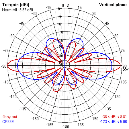
The four bay antenna has many more little lobes above and below and a slight asymmetry due to its mast. Still it manages an impressive 8-9 dBi where the variability is due in part to its not-quite-omni-circular pattern. The vertical beam-width matches what you expect from an 8 dBi antenna. It’s unclear what Diamond Antenna was thinking when designing their promotional information. The CP22E is a very impressive antenna and 5 dBi in a nine foot 2m antenna is a design win. Why Diamond misrepresents their antenna gain is anyone’s guess. It appears the engineers and product teams did not share much information back in the day of its design.
Disadvantages
Amateur radio trends lean towards a dual-band antenna with 2m and 440. The offerings are numerous. The performance good (despite almost universal gainflation specs). With this and other things in mind, some disadvantages of the CP22E include:
- 2m only – In the age of doing more with less, a dual-band antenna rules the roost. A mono-band antenna is limiting in many circumstances.
- No faking 440 – Unlike some 2m antennas, the CP22E won’t resonate well on the 3rd harmonic and even if it could the antenna pattern is hopelessly ridiculous.
- Lightning survival questionable – The aluminum tubing is quite nice, but would likely vaporize during a direct hit.
- Modest 200 watt power rating – The high-pass matching circuit and, perhaps, the inductor between the two collinear elements are likely the weakest link for power handling and a potential failure point. Budget conscious companies too often lowball passive components for matching sections that act more like a fuse at high power levels.
- Tiny assembly screws and other puny bits of fastening components guaranteed to vanish forever if dropped. Loctite on the threads is a mighty fine idea.
Advantages
- Fantastic electrical design – A lot of innovations exist in the CP22E design yielding about as good a mono-band 2m collinear gain benefit as is possible.
- An old design – The CP22E apparently has been around a long time and probably was designed well before the aid of computer modeling. Not dogging computer modeling at all, but am giving deserving kudos to the original designers.
- Lightweight – With weight under a few pounds, the CP22E is easy to handle.
- Low viz profile – Unlike many fiberglass encased antennas, the aluminum tubing is relatively thin making for slim lines in the sky.
- Low wind loading – There is no question the slim elements keep wind loading much lower than many fiberglass encased antennas.
- Cheap – You can get these on sale for about $50 or about $70 regularly. Yeah that’s not exactly free, but you do get some solid electrical engineering along with sturdy mechanical design for the price.
Conclusion
In the era of progressive economics and tightening wallets, value and return on investment rank high on buyers’ minds. To be honest most new hams with their new 2m/440 rig are best served by one of the many choices of dual-band 2m/440 antennas on the market. One rig, one coaxial cable (don’t scrimp here), one antenna and you’re all set. However…
- Don’t need 440 for some particular reason?
- Want to squeeze every last bit of 2m performance possible from your radio components?
- Need that sleek, XYL friendly, appearance?
- Have concerns about wind loads and your mounting circumstances?
- Can you live with a mono-band antenna?
Then the Diamond Antenna CP22E may be just the thing.
The Diamond Antenna CP22E – 5 dBi for fifty bucks.


Fantastic review, although reasonably above most Amateurs heads now days (some of which written here, mine included) however, a well written review to put the money where the mouth is. Electrical/Math fundamentals do not lie and this has proved that. THANK YOU for the time reviewing this product in such enormous detail.
K5BLS
Hello,
I have been Using the CP22E Antenna now for a year and it performs as advertised if not better,mine is 42 feet up on one of my towers and with my Radio Shack HTX 212 I can Hit repeaters all around me 32 Kilometers or more @ 45 watts ,I am a retired US Marine living in the Philippines and even though this antenna is for US 2 Meters it works well here.
73 de Bob DW7NIB good on QRZ and Hamcall.net
Dear Bob, good afternoon. I only had such an antenna for a few hours. The capacitor in the matching device burned out when 200 watts of power was applied. Replaced it with a new one. The antenna stood on the roof of a house 150-160 feet high. 180-200 miles connection. In a strong wind, the antenna broke in the middle. I came across a Chinese fake made of low-quality metal. In Russia, it is difficult to buy the original, there are many fakes.
Hi John,
Nice review. I have a damaged CP22E, and was considering using for LMR just above the 2M (about 156MHz). Do you think it would be possible to trim the elements for this range, or would that really mess up the patterns?
-Scott, NS7C
As with all end-fed collinear antennas, the phasing between the lower and upper current peaks relies on proper phase delay through the little inductor between the upper and lower sections. The causes the vertical angle of the pattern to vary with frequency. This effect is measurable between 144 and 148 MHz, but is so small to be of little consequence. 156 MHz might be possible, but this likely requires twiddling with the lengths quite a bit and then maybe also replacing the stock phasing inductor with a homebrew replacement. Then there is the matching circuit in the base designed specifically for the current CP22E factors. I'm going to venture to say retune of the CP22E may well be possible, but probably not practical without some serious engineering effort.
I bought this antenna and did not appreciate it because the top half bent over in an 80 mph wind storm so I took it down and forgot about it. Before I did I fixed it, taking the top half off and turning it upside down , inserting it into the bottom.
I'm using a 2 meter radio but figured I'd buy a dual band because I was told this $200 Comet was the bomb! I tried another Diamond dual band too.The CP22E blew them both out of the water. This is a good antenna for 2 meters. I wiped it down with a cloth and it rang like a tuning fork. I put my old fixed CP22E back on my 20 foot tower and it works perfect. For the price get an extra one in case it gets bent LOL. The review is spot on.
Purchased one of these about a year ago. Have fought high SWR's the entire time. Changing coax to grounding to heightening, nothing has been good enough to get below a 2.4 reading. Not even purchasing a new meter. Says no adjustment needed. Anyone know a remedy for me? Replaced with 102" whip and SWR reading dropped below a 1. Help!!
Nice review! Thanks!