Coaxial cables 1/4 wave long serve a variety of useful purposes in antenna assemblies. Whether it is the phase delay line for a Turnstile Antenna like the 80 meter Turnstile Antenna or to make the feed lines for a four-square antenna, the transformer action of a 90 degree long feed line serves many purposes.
Coax Transformer
A transmission line 90 degrees in electrical length “will have a purely resistive impedance when terminated with a pure resistance.” [1]
Two methods of creating a quarter wave long transmission line come to mind: Calculation and Measurement.
Calculation of Quarter Wave Stub Length
The most straight forward method of calculating the electrical length of a piece of coax involves first calculating the free space wavelength of the target frequency and multiplying by the velocity factor of the coax.
Coax velocity factor of popular coax cable types is published in many places. Two come to mind: RG58 has a Vf of 0.66 and LMR-240 has a Vf of 0.84.
So…
If you need a 1/4 wave piece of coax for, say, 7.150 MHz start by calculating the freespace wavelength…
Wavelength(Freespace-7.150MHz) = 300m/s / 7.150 MHz = 41.95 meters
…divide this by 4 to get 1/4 wave…
41.95 meters / 4 = 10.48 meters
…and if you are an Imperialist like me I convert to inches…
10.48 meters * 100 cm/m * 1″/2.54cm = 412 inches
…or about 34.5 feet.
Now take this and multiply by the Velocity Factor of your coax.
For RG58 -> 34.5 feet * .66 = 22.71 feet.
For LMR-240 -> 34.5 feet * .84 = 28.9 feet.
Depending on what you are doing with this quarter wave piece of coax, this may be perfectly adequate accuracy. Plus if you are dealing with HF frequencies the extra length added by connectors is not a major contributor towards phase angle accuracy.
However, what if you have unidentified and/or low quality coax and are not quite sure of its Velocity Factor? Measure it… electrically…
Measuring Electrical Length of Transmission Lines
Quarter wave and half wave length piece of transmission lines have special properties. A line quarter wave in length acts like an impedance transformer. A short at one end will appear as an open at the other. Likewise an open at one end will appear as a short at the other. This will happen only at the frequency where the line is 1/4, 3/4, 5/4, etc. waves in length.

Transmission lines a half wave in length come full circle by mirroring the impedance on one end to the other. An open circuit at one end will appear as open at the other. A short at one end will appear as a short at the other.

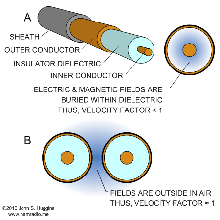
Note in both figures above the distance a wave travels is shortened by the dielectric properties of the coaxial line. This fact is represented in transmission line characteristics as a variable called Velocity Factor… a unit-less number indicating the fractional speed of light in transmission lines with respect to the free-space speed of light.
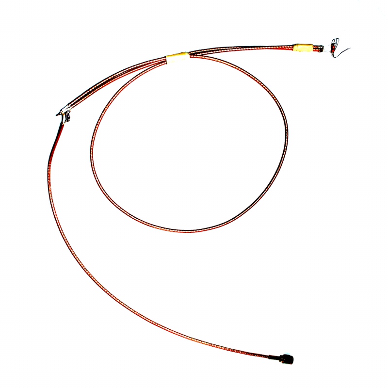
So let’s apply the above concept to this 182.5 inch piece of RG58C/U coax from Pasternack I have laying around the shack.

Let’s find the frequency where this piece of coax is a quarter wavelength and a half wavelength. Since the end of the coax is terminated into nothing, it is an infinite impedance. In the quarter wave case this infinite impedance will transform to zero impedance; We should adjust the frequency for minimum impedance…
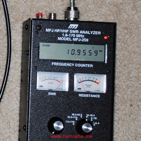
Those of you with later model MFJ meters have the advantage of seeing complex impedance. Adjust your frequency for minimum impedance and zero imaginary component.
We measure about 10.9 MHz. The accuracy of this method with this MFJ meter seems about +/- .5 MHz so this not an ultra precise way of doing this. However, it should be good enough for HF stub measurement.
If our goal is to make a 1/4 wave stub at 14 MHz we simply take out our coax cutters and snip off portions to raise the 10.9 MHz to 14 MHz. After each snip, adjust the frequency up and down to find the new zero impedance point. It’s that simple. When you cut the coax, be sure pieces of the shield braid do not short to the center conductor or you will suddenly be reading a high impedance at your meter.
Let’s raise the frequency of our meter to seek out the half wavelength frequency. Intuitively, this should be exactly twice the 10.9 MHz measured before.
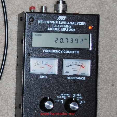
Well, we didn’t quite reach 21.7 MHz, but then again, it seems a bit more difficult to measure the center of a high impedance than low.
Continuing to raise the frequency allows us to discover another zero impedance point at 32.7 MHz. Again, accuracy is about +/- .5 MHz as it was difficult to really nail down a particular 1/10 of a MHz. This is pretty close to 1.5 times the half wave frequency of 21.7. We have found the point where the coax is 3/4 waves long.
When doing these calculations you should ensure the low impedance point is really the 1/4 wave rather than 3/4, 5/4 and so on.
Velocity Factor Calculation
Interestingly we have enough data to compute the velocity factor of this piece of coax using the measured frequency. We first take the 182.5 inches and compute the frequency of the free space wavelength…
We measure 10.9 MHz.
This is pretty close to the published RG58 Velocity Factor of 0.66.
- Gerald L. Hall et al. “Transmission Lines” ARRL Antenna Book. The ARRL, Inc. 13th ed. 1974. p 86.
You might want to rethink this;
"If our goal is to make a 1/4 wave stub at 7.15 MHz we simply take out our coax cutters and snip off portions to drop the 10.9 MHz to 7.15 MHz. "
If you snip bits off then I would suggest the frequency will go up not down
Egads… you are correct. Article fixed. Many many thanks.
Thanks for the article. I also use an MFJ antenna analyzer for this and it does just fine. But to prove my findings I hook the 1/4 wave piece to a T connector with the far end of the 1/4 wave coax shorted shield to center. Then I connect the other two ports of the T connector to a 50-ohm dummy load and an SWR meter. The SWR meter then hooks to a transmitter. When you TX on the frequency the stub is on you will get a good SWR, this is because the Stub is not seen and the dummy load is. As you vary away from the stub frequency the SWR will rise. This proves out the stub using a second simple test. We used shorted 1/4 wave stubs and T connectors for lightning protection for 10s of years at the State of Illinois Radio Lab to protect our base radio equipment. Hookup to the T connector was antenna in one port, 1/4 wave shorted stub in another, and the Base station or repeater in the last port. An SWR measurement was taken on the combination before leaving the site. Also the shorted end of the stub gets connected to the transmitter site ground. This worked very well!
Your setup is interesting, but not clear. You say "I hook the 1/4 wave piece to a T connector " In a T connector, there is the common "port" , which is the bottom point of the letter T. (either male or female), and the other 2 "ports",which are the ends of the arms of the letter T( either male or female)..Now, could you please resay what did you connect to what "port", using the above description?
Sniping coax to get to a wanted frequency has a danger. You may snip more that you wanted and will then be sorry. In addition you may end up with lots of snipped pieces of coax. Far better to use a short at the end of a coax method. The short is made with a darning needle and can be moved further or closer to lengthen or shorten the stub.
But remember, the short will now be 1/2 a wave length away not a 1/4 wave length.
You will end up with no snipped pieces of coax just coax with a few tiny holes that can easily be 'patched' with your favourite glue and I leave the simple maths to you.
73 de Pine, ZS6GST from the land with the big five.
But remember,
With a different analyzer which showed complex impedance I was able to determine the true quarter wave and velocity factor which was not as advertised for my coax . Supposed to be 88% but was 80. But, wondering if it could be done at vhf frequencies. One analyzer I had seen went up to uhf and it would probably have no problem.
I know this is an aging thread, but thought I'd mention the method I use. I took a PL-259 plug and socket and wired them back to back with a 50 ohm resistor connecting the center pins, and the shield sides of the connectors soldered together. The plug is screwed into the MFJ and the test cable is screwed onto the socket. When the MFJ is sending a signal at the frequency where the test cable is a 1/4 wave, the cable looks like a short at that frequency and the 50 ohm connection is completed to ground. A SWR dip occurs at that frequency.
I know this is an old thread. So don't know if you are likely to respond. What I was wondering is, can you explain the thinking behind this please?
I seem to recall that the MFJ is designed/calibrated to give accurate SWR and impedance readings only at/around 50 Ohms. So using the 50 Ohm resistor would make sense. After all, we are trying to detect a short at the end of a 1/4 WL line with 50 Ohms impedance. Have you tried the test with and without the resistor, was there any difference?