Ah the PL-259 (and its sister SO-239) connector. No one connector has engendered more commentary on performance issues than these. Humorously these connectors also have the name of ‘UHF’ Connector as if to suggest they perform well at 300+ MHz.
Once upon a time, when the PL259 was born, 30 MHz was UHF.[1][2] What was a connector designed during or before WWII[3][4] when Ultra High Frequency meant anything above 30 MHz[1][2], the unfortunate evolution of the UHF definition followed the PL-259 with it causing some to actually believe it works well at UHF.
This belief has become its own religion in some circles where defending the PL-259 against all foes trumps any real understanding of actual performance.
Some actual tests have been done to measure PL-259 performance. VK3JEG has an extensive set of notes on the subject at…
K7FR designed a very clever test to measure the power loss through the connector by measuring the heat generated by the loss.
This post was a response to another’s observation…
“I keep seeing this thing about connector loss everywhere I look. It’s become accepted as fact in our community, but it’s folklore.”
…
“With .1 dB loss per connector, power loss in a PL-259 SO-239 combo would be about 35 watts at 1500 watts.”
…
“35 watts of connector heat (with a 1500 watt transmitter), when concentrated in the inside of the SO-239, would quickly make the connector so hot it would be untouchable. In a few minutes melt the solder connection and dielectric.”
Folklore? Well not in the lab certainly as we will show.
Reflective loss yields no heat at the impedance discontinuity
The underlying assumption with the above statement is connector loss has everything to do with resistive “heating” losses, has nothing to do with reflective losses, and all loss will reveal itself as heat energy.
The same assumption is made by the otherwise informative amateur’s web post [5]…
A High Power “Calorimetry” Test — Here is my observation. I took a 432 MHz Stripline Parallel Kilowatt Amplifier and applied 700 watts through a UHF female and a UHF male connector, and then into my antenna feed line. After 10 minutes of 700 watts throughput power the UHF connectors were mildly warm. If I estimate that “mildly warm” represents a dissipation of 3 watts out of 700 watts, that’s an estimated insertion loss of 0.019 dB for the pair of connectors. You’re about to ask, “how can this be, the internal dimensions are approximately a 35 ohm impedance, it’s got to cause a 1.43:1 VSWR?” Well, it doesn’t.
Let’s clear up this point right away. Connector loss is two things: resistive loss and reactive reflection loss. The former is simply the loss due to the resistance encountered by the signal on both the center pin’s outer surface and the shell’s inner surface (skin effect). The later comes about when the impedance experienced by the signal changes abruptly causing some of the energy to simply reflect back towards the RF source.[6] This reflected energy generates no heat in the connector and, thus, cannot be measured by a calorimeter.
A reasonable question is “Where does the reflected energy dissipate?”
The energy bounces back into the RF source and is dissipated as heat in the source impedance and/or re-reflected back towards the load depending on the source’s circuitry. The final transistors in our radios are where some, if not most, of this energy turns to heat. This is one reason why finals fail and why our radios scale back output power if it notices it coming straight back into the radio. (Another reason for final failure is high voltage resulting from the standing waves exceeding the transistor’s ratings, but that’s another story.) There is debate on how and why energy might reflect back from the source towards the antenna. Look up Maxwell’s “Reflections” publication for details.
So…
Though very ingenious, connector heat detection methods are of no use in critiquing transmission line performance.
S11 and S21 – the right way to measure
What tests should be done to properly assess connector performance? Two come to mind…
- S21 Test – Measurement of loss through a system.
- S11 Test – Measurement of return loss of a system.
The S21 test simply reads the amount of energy passing through an article under test by feeding one side with RF energy and measuring the energy flowing out the other side. Things with active amplifiers may show gain. Passive devices always show loss. The value is expressed in dB where 0 dB is no loss and no gain.
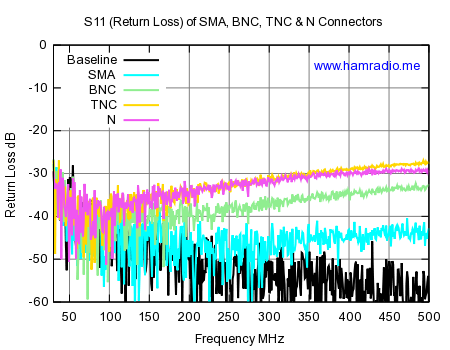
The S11 test measures the amount of energy that bounces back from the article under test due to impedance mismatch. It is expressed as a ratio of power received back over the power delivered and is measured in dB. The greater the number, the less energy is reflected back to the RF source.
By measuring both the energy passing through and bouncing back from the device under test we can find out where the energy is going and see if the energy is turning to heat or getting through to the load.
What gear do we need to do our own test? One answer is a Vector Network Analyzer (VNA). Good VNAs calibrate their test cables so they are not part of the measurement. This leaves only the article under test in the spotlight of measurement.
Another quote[5]…
UHF Connector Maligning — There are many misinformed engineers and amateurs who have been led to believe that a UHF connector is the worst thing ever invented in the RF world — due to it’s lower internal impedance. They believe that each UHF connector causes a 1/2 dB insertion loss and a whole lot of VSWR at 432 MHz. I’ve heard quite a few amateurs claim that their 432 MHz brick amplifier will now have 1 dB greater gain since they just replaced the two chassis mounted UHF connectors with Type N connectors. This “Old Wive’s Tale” has been propagated for decades. Everyone believes it. No one challenges it. Few people have ever [made] the measurement.
Fair enough. Challenge accepted.
Let’s measure the UHF and other connectors
I will include various connectors, both old and new and see for myself if this really is an Old Wive’s Tale.
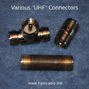
In the photo below we see a few ‘UHF’ items which we will test…
The above aren’t exactly connectors in the sense of devices at the ends of cables, but serve the purposes of this test just fine. During the actual test, there will be two TNC to PL-259 converters used to adapt these devices to the test jig. Since the length of the ‘barrels’ and tee above are different lengths, we will see first hand how the lower impedance of the PL259/SO239 world affects the transmission path.
In addition we will test N, BNC, TNC and SMA connections to compare against the PL259/SO239 connectors.
Lastly we will search for a standard connector that is worse than any of the above and test that too.
In the next post we will examine the various items we will test and in following posts reveal the measured data.
However, let me reveal one outcome of the tests I performed… The ‘UHF’ connector works just fine at frequencies below 30 MHz… as it was originally designed to do oddly enough. So despite the mechanically ridiculous mating scheme and completely absent moisture resistance, the UHF connector is just fine, electrically, at HF and below. This is true of any deviation from the controlled impedance path so long as that deviation distance is much much less than the wavelength of the RF.
References:
- “Introduction to U.H.F.”. The Radio Amateur’s Handbook (18th ed.). West Hartford, CT: American Radio Relay League. 1941. pp. 362–363.
In Amateur work, the ultra-high-frequency region is considered to include the 56 to 60 Mc band and all higher frequency bands available for amateur use.
- Table I: Classification of Frequency Ranges,” Section 15, Radio Engineering Handbook by Keith Henney (Fellow, IRE), 3rd Edition, 1941, McGraw-Hill, New York
- US patent 2335041, William A Bruno, “Right-angle electric connector”, published 1943-11-23, assigned to Bruno Patents Inc
- US patent 2422982, Edward Clarke Quackenbush, “Coaxial cable connector”, published 1947-06-24, assigned to Edward Clarke Quackenbush
- “How much better is an N over SO-239 at VHF/UHF?” – E-Ham.
- US patent 2233166, William C Hahn, “Means for transferring high frequency power”, p. 1, col. 1, lines 9-14, published 1941-02-25, assigned to Gen Electric
- The UHF Connector


Motorola used UHF connectors on uhf base stations and repeaters running 250 watts and they were just fine.
And their 250 watt duplexers were among the lowest loss in the business with again UHF
connectors.
If you use cheapskate han operator connectors, sure you may have some problems.
This is why the ONLY ones who ever cry about PL259s are hams.
The larger problem with the UHF Connector is the lack of any standard way to make them. Most, but not quite all, get the mechanical aspects correct, but electrical specifications are no longer, and may never have been, specified anywhere. Embarrassing.
This article might shed a little more truth on the argument : https://www.iz2uuf.net/wp/index.php/2016/01/08/pl…
David's conclusions match mine, which is, no appreciable difference at 430 MHz.