An airplane mechanic friend, who also happens to own a 35 year old single engine Cessna airplane, was working on his tail light when he saw broken and aging components in his tail mounted navigation antenna. While working to fix the problems he discovered an interesting balun technique.
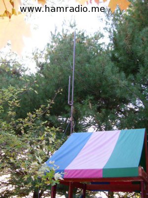
These antennas are usually just two 1/4 wave dipole elements mounted horizontally on the top of the rudder.
This seems the obvious place to use a balun to take the unbalanced coax and connect it to the balanced antenna.
Indeed, this appears to be what Cessna has done and this fellow’s airplane receives good comments about its receiving capability from the pilots who fly his airplane.
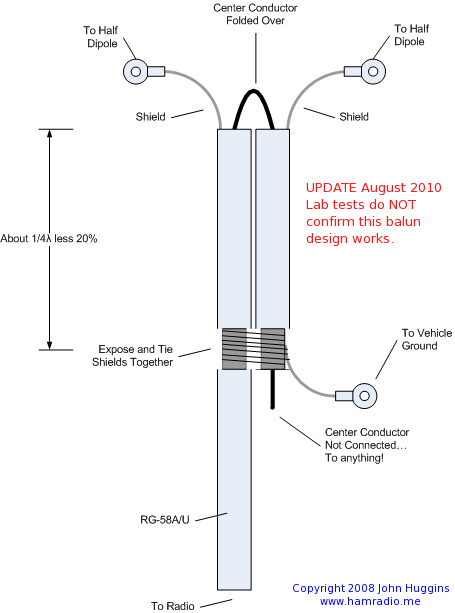
So here is how the antenna coax is arranged to connect the dipole to the coax…
Note how the center conductor never ever electrically connects to anything. It would appear there has to be some capacitive coupling in the 1/4wave – 20% section.
As this has been operating in the many hundreds of Cessna aircraft built over the decades, this, quite obviously, works. Can any one of you viewers of this web site explain why?
Thanks.
UPDATE 2011:
Further research indicates the above topology is a form of “Roberts’ Balun” initially designed many decades ago in 1957 for FCC field work by Willmar Roberts[1].
This is a somewhat like a Folded Balun with the addition of feeding the center wire of the coaxial line back into the stub.
The result is two contra-frequency-dependent effects which broaden the usable frequency range of this assembly.
Clever.
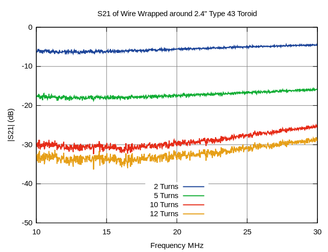
The Roberts’ Balun examples I found usually have the looped center conductor terminate inside the stub rather than go all the way through it. This may be why the above example doesn’t seem to function well in the lab.
References:
- Proceedings of the IRE, “A New Wide-Band Balun,” Proceedings of the IRE, Volume 45, Issue 12, pp 1628-1631; December 1957.
Per ANSI C63.5:
"The shorted balanced line and the open coaxial sections appear in parallel and series with the load, respectively. The parallel section forces the load to be fed in a balanced manner. Although the use of a parallel shorted stub alone will affect a balanced to
unbalanced transformation, it provides a useful match only over the narrow range where the stub presents a high impedance. The combined action of the series open stub and parallel shorted stub extends the range of approximate match. The two matching stubs are one-quarter of an electrical wavelength at the center of the frequency band in which the balun is intended to operate. At the center of this band, where both stubs are resonant, the series coaxial-line open stub looks like a short circuit, while the parallel balanced-line shorted stub looks like an open circuit."
Equations for the stub impedance are:
For a series stub,
Zs = jZo cot θs
For a parallel stub,
Zp = jZo tan θp
where
θs, θp are the electrical length of series and parallel stubs respectively, and
Zo, Zp are the coaxial and balanced line characteristic impedance, respectively.
One thing to remember about the balun used above is, the design is meant for RG-58 solid insulation, not foam insulation and black PVC outer jacket.
If you change any part of the design, you need to recalculate the lengths of the two stubs. RG-400 and other coax can be used, but not at the same lengths, due to the change of velocity factor of the center insulation and jacket velocity factor as well. The stubs need to be 1/4 wave length electrically, and the closer to 100% the VF is, the longer the stubs will be.
I saw this design used in2-element 2m Portable quad article in &# 0r CQ way back in the early 90s. .I adopted it for my Twin-Folded-Dipole Yagi for 2 meter. I used RG58U cable. It worked.