Update September 23, 2017
The article below describes an antenna designed to accommodate 470-700 MHz. Recent actions from US regulators are lowering the top end to about 614 MHz negating the advantages of some broadband designs. As you will read below, Hoverman’s original design was limited in frequency range of 470-602 MHz. With the mods below, the new Hoverman is still a design win for the UHF TV spectrum, but may need to compete with newer, cheaper or simpler designs tailored for the lower bandwidth.
Superbowl in HD
There are claims the digital TV signal you receive from broadcasters via over-the-air (OTA) transmissions is or can be higher quality than what you get from cable or satellite service.
I don’t have enough viewing experience to know one way or the other. However, I’m always up for a challenge.
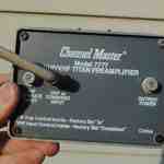
My TV has an ATSC (modern day digital television standard) receiver built right in. However, at 40+ miles from DC, I know I need a good antenna. My aging Channel Master 4228 is falling apart. I decided to try something new… or is it old…
Background of the Hoverman TV Antenna
What follows is a step by step photo shoot of my version of the venerable Hoverman UHF TV Antenna based on a design from the late 1950s. This all came about to finally obtain off-the-air (OTA) signals for our TV. I have a crumbling Channel Master 4228 (old style). The 4228’s design provides coverage for the old much wider UHF North American television band – 470-890 MHz. That’s fine, but times have changed and new antenna designs focusing on the today’s smaller 470-700 MHz are sensible.
What’s old is new
The Hoverman UHF antenna design is not new. The original US patents #2918672 and #3148371 date back to no later than 1964 with Doyt Hoverman as inventor. The initial patent describes the zigzag driven element common to both patents.

The driven element is simply a wire bent as shown with straight sections about 7 inches in length. “FP” marks the ~300 ohm feedpoint. The next figure shows how Hoverman arranges these two zigzag elements in front of horizontal rods in various configurations to make the antenna unidirectional. Click the figure to show an enlargement.

The “Fig 1, 2 and 3” reference the same Figures in the later patent. Figure 1 shows four continuous reflecting rods about 1 wavelength at the high and low frequencies in green electrically connecting to the vertical structure, also in green. Figure 2 shows pairs of electrically isolated reflecting rods about 1/2 wavelength of high and low frequencies in blue; Hoverman notes this has the best performance of the three. Figure 3 shows a hybrid of Figures 1 and 2. Figure 4 reveals the distance between the driver elements and reflecting elements to be 3.5 inches.
Back in the 1960s, the UHF TV band ranged from channel 14 to 83 – 470 – 890 MHz. Hoverman explains his example dimensions cover UHF TV channels 14 to 35 – 470 to 602 MHz. Recognizing the frequency limits of his antenna design, Hoverman suggests to scale the dimensions smaller for the higher channels. In other words his original antenna was unable to cover the entire UHF band.
What Hoverman could never have known is how the UHF channels shrank over the years from 14 – 83 to 14 to 51 yielding today’s 470 – 698 MHz. Now Hoverman’s antenna design almost covers the current UHF frequency range… but not quite.
NEC Geeks to the Rescue
In 2007 antenna enthusiasts took a fresh look at Hoverman’s design and performed extensive computer modeling using versions of Numerical Electromagnetics Code (NEC). The resulting modifications to Hoverman’s original design yield an antenna with good gain and modest front to back across today’s 470-698 MHz UHF television band.
Their most significant contribution was to shorten the extensions on the driver a couple of inches increasing the top frequency of the original Hoverman to just cover the entire post 2009 North American UHF TV band.

Much of the enthusiasts’ re-design effort centered around the “reflecting” elements behind the zigzag driven elements. Summarizing, these new designs use additional rods or screens to optimize the antenna including:
- The above Modern Hoverman driver in front of six pairs of collinear rod reflectors with refined spacings designed by the Digital Home participants – This is the only documented design they placed in the public domain via an odd saga and misapplication of copyrights to their idea;
- The above Modern Hoverman driver in front of a 30 x 40 inch split reflector screen (two Digital Home participants;
- Two of the above modern Hoverman drivers in front of eleven pairs of collinear rod reflectors with refined spacings designed by the Digital Home participants;
- Two of the above modern Hoverman drivers in front of a 30 x 75 inch full screen reflector designed by the Digital Home participants;
- A highly optimized Hoverman style driver element pair in front of ten pairs of collinear rod reflectors with precisely refined spacings designed by John Davis.
Rods are clever – screens are simpler
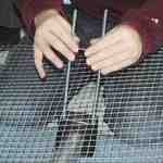
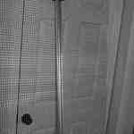
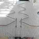
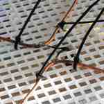
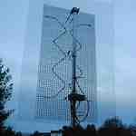
My modeling shows a single Hoverman zigzag element pair over a full screen works adequately, making assembly of the Hoverman much simpler than these other approaches. Plus I found the full screen mesh promises much higher front to back ratios than any rod reflector approach. This is important if you need to select one broadcast in a particular direction sharing the same RF frequency with another broadcast in a different direction.
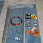
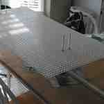
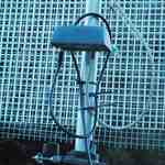
I decided to place the Modern Hoverman Antenna Driven Element over a 3 x 4.5 foot galvanized mesh screen. I made good use of parts from DX Engineering with the rest coming from a home center and a hardware store.
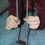
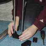
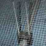
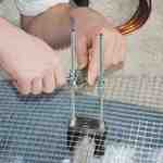
Build the Screen Hoverman
Here are some pictures of KJ4FAJ and brother building the Hoverman TV antenna… click any picture for more details.


Notes
- I did not include the price of a new rotator or cable in the antenna cost above. All told, I probably sunk about $150 into this project and that doesn’t include the preamp I pulled from the old 4228 antenna.
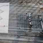
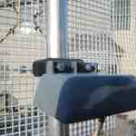
- The aluminum mast serves both as mast and antenna backbone. This is different from most antennas that provide their own skeleton support. This dual use technique saves quite a bit of weight in the final assembly.
- The most exotic parts in my version of this antenna are the Resin Support Blocks and corresponding reinforcement plates from DX Engineering. These were key in making the 1.5 inch aluminum mast serve also as the backbone of the antenna. It just so happens the bolt hole spacing is just right to bolt the preamp on as well… nice.
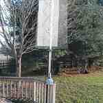
- I’m able to pick up all DTV stations in Washington DC (~45 miles) and Charlottesville (~58 miles) with the center of the antenna a mere 7 feet above the ground on a speaker stand. I can pick up WNVT in Goldvein as well, but that’s only 20 miles away… it’s a blowtorch.
- At 70+ miles, I am unable to pickup Richmond. A little bit of elevation should help.
- I easily receive the Washington ABC and CBS stations as well. This is significant because they broadcast their digital signals on their old VHF frequencies… RF channels 7 and 9 respectively. This confirms the Hoverman antenna with the full reflector screen has some usable VHF reception. If you use a pre-amp in an area with VHF digital broadcasts, make sure to get a model that supports VHF AND UHF, not just UHF.
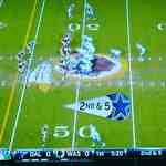
- I actually do like Tony Romo, but am a skins fan first. The rest of my family is for the Cowboys… sigh 🙁
Design for Manufacturing (DFM)???
Many resources on the web profiling this antenna mandate impractical millimeter precision when bending, cutting and assembling the Hoverman antenna. Well, that didn’t happen here! This thing was just about thrown up with sloppy bending of the copper wire and not very flat mesh reflector screen. All I can say is, at only 7 feet high, it works. How well you ask? Let’s look at a real measurement of the antenna pattern.
An actual antenna pattern measurement
NEC is a very powerful and accurate tool to help design antennas including the Hoverman. It is still nice to have a real measurement for peace of mind… and here is one with this new antenna.
WNVT is so powerful and close, I can see the main carrier (as well as the entire digital pedestal) quite clearly on a spectrum analyzer using the new antenna with the preamp. I used the analyzer to measure signal strength of the main carrier while rotating the antenna with the new rotator. Here are the results…

The light green line is the simulation response of this particular antenna design at 566 MHz using a 3 x 4.5 foot grid of wires with 1″ grid behind the modern zigzag driver; The actual grid is 1/2 inch, but 4nec2 coughed at so many wires; Yes, the smaller grid does make a small difference. I “fit” the 13.6 dBi peak gain and 48 degree beamwidth NEC curve to the 60 degree wide measured value so we can compare reality with simulation. This “fit” is only a guess folks, but not an unreasonable one.
Observations:
- WNVT is due east of my location and that is quite evident in this graph.
- The front to back ratio exceeds 14 dB at this one frequency.
- The pattern is not as symmetrical as I would like and contrasts with the perfect world of simulation. This could be due to reflections off the house to the north, the trees to the southeast, more trees due west, assembly sloppiness or other variables.
- The primary lobe is well defined and about 60 degrees wide which closely agrees with the simulation beamwidth of 48 degrees. As Tim Sample might say in Maine… “That’s mighty good.”
- This pattern may not be a textbook beam shape nor perfectly match simulation, but it has all the important points: Good front to back and good beamwidth. What’s the gain? Later measurements suggest about 14 dBi… a close match to the 13.6 dBi value from simulation.
- [WAG]The more I think about this, the more I believe the line of pine trees just 40 feet to the southeast may be diffracting some of the WNVT signal into the antenna.[/WAG]
Conclusions
Doyt Hoverman was onto something back in the late 1950s and early 1960s with his odd zigzag antenna design for UHF TV. Modern computing has refined this concept to yield a very usable antenna for the modern age of digital television.
Professional antenna designers likely see a distinct similarity of the Hoverman zigzag element to the modern wideband flared dipoles.
This antenna is horizontally polarized. Some vertical polarization exists to the sides of the antenna, but when aimed correctly the result is definitely horizontal polarization. This matches most broadcast stations.
In an upcoming post, I will highlight the history of the Hoverman and show simulation results. Usually I would do this first, but some of you might enjoy watching Superbowl 47 with the above Hoverman antenna right away. The above actual pattern measurement plus my DTV reception tests suggest this antenna does work.
Most of the components for the antenna are available from local outlets with the exception of the aluminum mast (I got mine from Grainger) and the handy resin support blocks and plates from DX Engineering. The rotator from Radio Shack is perfectly adequate and available locally. I do use an NTE TB-105 bearing with the rotator for a much more stable system; I would never place this tall an antenna directly on the rotator, but that’s my opinion. The bearing comes with three convenient guy rope tie points which I do use at the moment. The rotator and bearing mount on an aluminum speaker stand I had handy for convenient yard use and testing. The ultimate goal is to place the antenna atop some taller support, but I have no idea what that may be at the moment. Currently, my family enjoys the antenna as is so until football season is past, I’m not changing a thing.
If you are looking for a straightforward way to receive broadcast TV in remote locations, the Hoverman antenna is well worth a try. Unless you are very close to the transmitters, you should get a good preamp and mount it on the antenna as I have done above. Consider a light duty rotator if you will regularly point the antenna at different metropolitan areas. Remember, the investment you make in a TV antenna pays dividends with free programming.


As you said, the links on http://www.digitalhome.ca/ota/superantenna/ are dead for some reason. But you can find that info on this contributors website. http://clients.teksavvy.com/~nickm/gh_u.html
The site was archived, you can see it here: http://web.archive.org/web/20160326075106/http://…
hi i am va1dwg just wondering how that antenna could be cut to serve 220 mhz or 440 mhz. band . ham radio thanks
I wonder if some one could give the specifications for a Gray-Hoverman wifi antenna ?
I have an old 2 meter antenna, I believe it was called a waterfall It is setting there doing nothing I am going to add this to it and see what it dose. I will report and take a few photos as I go. Guy
I am building a DBGH using the plans found on various websites. I have seen one inconsistency between the plans that is confusing me on the length after the last bend on the driven element. I under thank the original plan called for 7" which was revised to a shorter length for higher gain. The question is what is the correct length? I have seen plans say 5" or 5 1/2" or even a 5 9/16. Which one is best? If it depend on the channel I want the gain on then I prefer the highest gain to be on 33-39.
John,
The original Hoverman design had limited frequency range. That ~5 inch length is indeed the primary refinement of the more recent Hoverman designs (7") and it extends the frequency range of the overall design quite a bit upwards. With the abandonment of the upper television channels this is less important now. To answer your question more directly… While 16ths of an inch precision might matter in a perfect NEC model, I'm not convinced manufacturing tolerances for any given build are going to be accurate enough to make the length of that last element more critical than, say, 1/2 inch precision. That was certainly the case with my example above and it tested very very well in chamber measurements.
Thanks for the reply and that great info. My DBGH build is almost ready 7 1/16" I just need to add the reflector. The gain chart shows the dbgh peaks on channels 42-50 https://www.digitalhome.ca/ota/superantenna/NetGa… is there any way to move this peak down to channels 33-37 by cutting the length 5" length or using the right size reflector rods or screen? I probably should have built the GH6 narrow band but I'd rather not rebuild this. Channel above and below this range should work with a lower gain. Also, Is there a working NEC 2 file I can at least chart the gain?
Built one with copper tube (3/8" flexible), 2" PVC as a mast and some electrical tape and put it on top of my house (3 stories). Antenna is 12 ft above the roof and it reaches 130 miles. I'm near the Missouri river in south central south dakota and pick up Worthington mn.
I'm curious about why your antenna is wired parallel, I have a PDF of the patent and HH says that it should be connected in series. Not that it makes any difference, just wondering if you did it for a reason.
This https://patents.google.com/patent/US2918672A/?
I see references to the series connected V shaped elements alluding to the bent structure of the radiators….
"each section comprising three series-connected V-shaped elements arranged in end-to-end relation thereby providing three"