Summary
At Field Day 2012, my project antenna was a version of the Loop Fed Array (LFA) Yagi-Uda antenna inspired by the hard core simulation efforts of Justin Johnson (G0KSC) [1].
With some adjustments made to accommodate copper pipe instead of aluminum tubing, the LFA design was easy to morph to an exotic “plumber’s special” beam.
The pleasing result shows simulation and measurements do actually agree.
The LFA also offers a special bonus with its, oh so easy, transmission line hookup.
The Flat Loop Fed Yagi-Uda
The concept of feeding a Yagi-Uda with a full-wave loop is not new. However, Justin makes good use of an old, tried and true, technique of laying it flat in the array so it is in the same plane as the rest of the elements. Adding a computer science approach to NEC modeling results in some impressive antenna design results. The earliest announcement of his work I could find appears in this April 2009 PDF…
Note: two weeks after this post, the above item was removed from the vinecom.co.uk site. Search for it on Google.
Read all about his work at his web site…
Copper vs. Aluminum
Justin’s simulation efforts focus around aluminum tubing for the elements. Being a copper freak, I sought to modify one of Justin’s LFA designs for use with home-center copper plumbing pipe for the antenna elements.
My first task was to select a design from Justin’s many offerings.
My goal was simple… field a 6m beam for Field Day. I quickly selected Justin’s smallest 6m beam…
Justin provides a link to a handy EZNEC file to begin. However, the link returns a 404 error. No problem since the dimensions are listed on the same page. I entered the dimensions into EZNEC, changed everything to inches, changed all the elements to 1/2″ copper plumbing pipe (OD of 5/8″) and then made adjustments until I found the best F/B and Gain compromises. Figure 1 shows the wire model of the result…
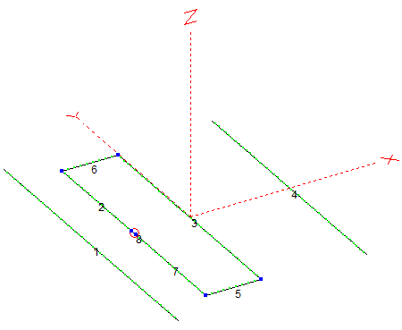
The only parameters changed were the element lengths to adjust the relative phasing. The element spacing was kept the same as Justin’s original design.
Some Simulation Results
This copper version with slightly different tube diameters required some element length adjustments, but Justin’s design was a great place to start. Figure 2 shows how well the tweaked LFA design achieves great front to back ratios at several frequencies…

This antenna provides 8.6 dBi gain with a 60 degree (+/- 30 degree) 3 dB beamwidth. You may be looking at the good control of rearward energy in complete disbelief. Figure 3 shows a closer view…

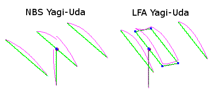
That’s some mighty fine f/b performance in a 3 element array and a marked improvement over the NBS Yagi-Uda. Note this pattern shape is very good, but not quite as good as Justin’s perfectly tweaked aluminum design. He has two nulls on each side… mine are a bit less defined. I was in a rush for Field Day 2012 and better was the enemy of good enough. I like it.
Why the LFA?
Justin’s goals with his design efforts include lowering noise for the VHF DXing and EME crowd. One easy way to lower noise pickup from around the antenna is to not pick it up in the first place. The LFA is designed specifically for this and these simulations confirm Justin has done a very good job of finding the right “recipe” to curtail pickup of energy from anywhere other than the front of the antenna.
Additionally, full wave loops tend to attenuate feedline currents by their very nature [2][3][4]. While referring to their full wave dipole loop antenna, Hayashida et. al. said:
This antenna has a one-wavelength loop structure so that no unbalanced current may be produced on the feedline; that is to say, this antenna has a self-balanced structure, […] [3]
This may well preclude the need for a balun. This may also be why Justin’s designs work so well despite the best efforts to spoil the balance with the various methods on his site.
Prototype the LFA
Simulation is one thing, but building the actual antenna is another. I used my NEC custom model, bought some materials and made my own copper 3 element 6m LFA and took it straight to Field Day 2012. The details on construction are in two posts about Cutting LFA Copper and Assembling the LFA, but the dimensions are available in a PDF at the end of this article.
Measure the LFA
I took time at Field Day to bring out a VNA and measure my 6m beam as seen at the end of a 100′ piece of Times Microwave LMR-240 Ultraflex coaxial cable. Figure 4 compares the SWR from simulation with measurements of the actual antenna…
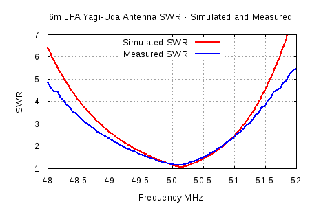
That’s about as perfect agreement as one is going to get between simulation and reality. Cable loss easily explains the slightly flatter response of the “measured” results.
It’s moments like these where I really enjoy antenna engineering. When your simulations match measurements this well, it’s time to pop the corks!!
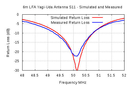
For my fellow antenna professionals out there, Figure 5 shows the same thing as Return Loss…
Copper Pipe LFA Dimensions
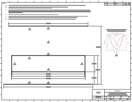
Figure 6 is a link to a PDF drawing of the copper version of Justin’s 3 element 6m loop-fed Yagi-Uda design.
Conclusion
The Loop Fed Array by Justin Johnson appears to be a winning design with benefits beyond the original goals. My copper variant was easy to achieve using his aluminum measurements as a starting point.
References
- Johnson, Justin (2009-2012). G0KSC – High Performance Antennas.
- Buxton, Carey G., Warren L. Stutzman, Randall R. Nealy and Aaron M. Orndorff (2001). The folded dipole: A self-balancing antenna.
- Hayashida, Shogo, Hisashi Morishita and Kyohei Fujimoto (2002). Self-balanced and wideband folded loop antenna for handsets.
- Uchida, H. and Y. Mushiake (1961). VHF Antenna. Corona Publishing CO,. LTD, Japan.
Hello,
Thank you for investing the time to photo and document the work, greatly appreciated! I’ve been planning to build a 6m and 10m G0KSC antenna to use in my attic and in our General Class “Antenna Construction” class. I like that the SWR plot is centered on the DX Calling window but I was surprised how it rapidly increases before even 50.1 MHz so maybe try ¾ inch copper? Have you tried bending the pipe instead of elbows and soldering? I was thinking of trying to borrow or rent a pipe bender but playing with a torch can be fun!
N5ZY
The 2:1 SWR range is 49.2 to 50.7 MHz. 50.1 MHz is well within the very good SWR range. Were you looking at 51 MHz? You can try 3/4 inch copper. The dimensions will be a little different – Simulation will help here. I think the 1/2 inch copper antenna likely has enough bandwidth for most CW/SSB 6m use.
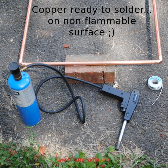
You can bend soft copper pipe, but then the resulting loop would have less structural strength. The stiff copper pipe (used for usual plumbing tasks) doesn't bend easily. Elbows are a good way to go I think.