J-Pole antenna grounding
Saying “J-Pole” conjures up thoughts of 2m vertical antennas atop metallic masts with a good solid connection to the earth. We assume it will function because we read “the mast isn’t part of the antenna” or “the antenna is naturally at dc-ground” or “the center of the bottom shorting bar on the J-pole should be at RF ground potential” or “support must be grounded metal for proper operation” on various internet ham watering holes. You will find a theory based debunk of these myths right here. It is time, however, to get past theory (and folklore) to see how a real antenna behaves with some actual measurements. Having a fully grounded antenna is certainly a very worthwhile goal so long as you don’t needlessly compromise the antenna’s functionality at its design frequency. Up till now my previous articles have confirmed the assertions of the “NEC geeks” with my own NEC and FDTD models. The time has come to see if this holds up in a real antenna if to, for no other reason, quell the chorus of simulation deniers. This article has two highlights:
- First it will confirm experimentally that masts do indeed draw current from the J-Pole antenna and then,
- It will experimentally show how to avoid this phenomena.
The goal is to confirm or deny if and how we can make the J-Pole antenna worthy of its lofty hopes.
Hypothesis
If the NEC geeks’ simulations are correct, the measurements should reveal mast lengths of:
- one or multiple half-wavelengths for the open ended mast which interfere little with j-pole operation,
- quarter-wavelength plus zero to multiple half-wavelengths for the open end mast that significantly interferes with j-pole operation.
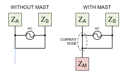
Of course in real life we would ground the mast so the above length conditions would swap. For this test, the end of the “mast” is floating. NEC theory suggests varying the length of the mast will transform the high impedance at the open end to the bottom of the J section and present a varying impedance to the feed source. This becomes the Zm in figure 1 and this article.
Test Plan
Every test needs a plan. Here is the bullet list for this 1 GHz J-Pole:
- Design j-pole antenna suitable for testing in a far-field chamber.
- Measure pattern of J-Pole and compare with simulation.
- Measure pattern of J-Pole with no mast and compare with other antennas.
- Measure return loss (and VSWR) of J-Pole with varying lengths of mast.
- Measure patterns of J-Pole with varying lengths of mast.
- Measure return loss (and VSWR) of J-Pole with mast stub and varying lengths of mast.
- Measure patterns of J-Pole with mast stub and varying lengths of mast.
- Prepare and analyze graphs of above data.
- Draw conclusions about the stub mast treatment.
Test Antenna Design
Antenna testing facilities tend towards higher frequencies so I scaled a typical j-pole configuration using 32 mil brass rod with dimensions targeting 1 GHz. As you will see below I hit 1.06 GHz, but that’s close enough to get the test underway. Figure 2 reveals how the test antenna incorporates the “mast” along with a proposed “mast stub” (described here) in the form of a simple stub just below the bottom of the J.
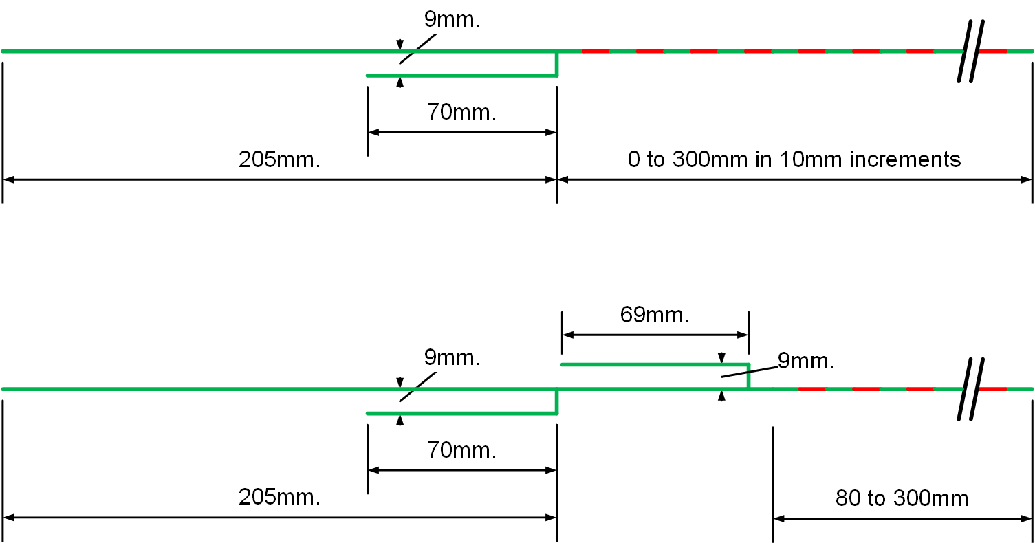
Figure 3 shows a photo of the test antenna with the mast stub in place, but no extra mast (this was after the test).
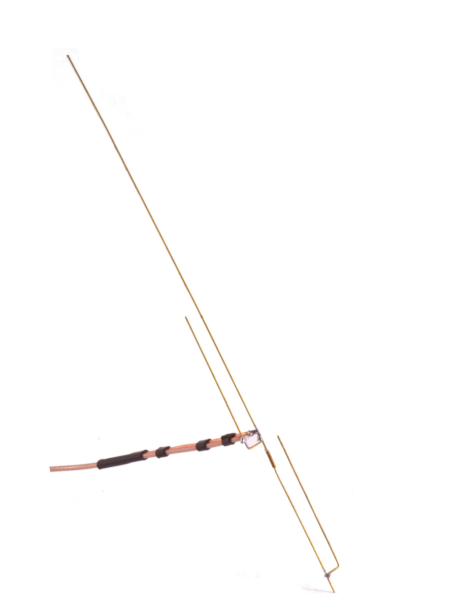
That’s a folded balun (aka Pawsey stub) feeding the j-pole constructed with a piece of 12 AWG solid copper wire next to RG316. Little bits of heat-shrink strap it all together. These things put the slam on feedline currents past the balun although they can be tricky in the parallel conductor area due to the external fields. This one behaves pretty well, but we oriented it perpendicular to the j-pole elements to ensure emissions from the balun would have polarization orthogonal to the main J and its mast. More discussion on this style of feedline choke is available here. For this test, SWR, return loss and far-field gain patterns were made while trimming the “mast” 1 cm at a time. The alternating red and green segments in figure 2 show the 1 cm sections.
Where modeling and reality agree
Before we dig deep into other data, figure 4 reveals the close agreement between NEC simulation and actual antenna measurement give or take a dB or so…
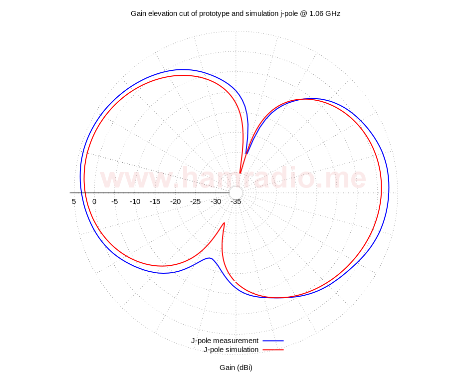
The test j-pole is fed with a folded balun with orientation perpendicular to the j-pole’s elements. Any emissions from this feed and the feedline have polarization orthogonal to the native “vertical” polarization. Both polarizations were measured, but the above plot only shows the primary “vertical” polarization. As you can see, the simulation of this very antenna closely matches the real measurement. This is step one in validating the NEC geeks concerns. Let’s test further to see more.
Results of testing 1 GHz J-Pole
Let’s head straight to the empirical data as this tells the story best.
Pattern of J-Pole with no mast

Figure 5 sets the stage by comparing the j-pole with a couple of monopole antennas: one with a metal sheet, the other with radials. The two monopoles were hand tuned to trim out reactance leaving only the real impedance at 1 GHz. The monopole over conductive sheet is no surprise, but the monopole with radials isn’t what I expect to see. Simulations suggest the monopole over radials – be they horizontal or angled – should have a pattern very close to the shape of a simple half-wave antenna. Adding the mast and/or feedline to the monopole simulation solves the mystery. Even if the mast is not directly connected to the antenna, the radials induce currents in it resulting in the above pattern. I mention this here so you don’t take the above graph to suggest the monopole looks this way after feedline and mast treatment… but deeper discussion of the quarter-wave monopole is for a future post. Figure 5 teaches us the following…
- The j-pole takeoff angles are slightly better than the monopoles (due to monopole feedline and mast),
- The j-pole has slightly superior gain over the monopoles.
Granted up to 0.8 dB additional monopole mismatch loss is attributable to the lower monopole feed point impedances, but the j-pole still has the edge in gain. This suggests having a full length half-wave radiator offers a slight advantage over the monopoles. Onward with more j-pole testing…
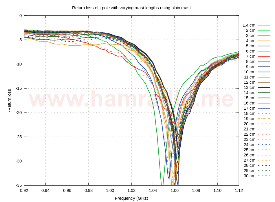
Return loss of J-Pole on varying lengths of mast with and without the stub
This is a test anyone can do using one of the new amateur level network analyzers coming on the market. Figure 6 reveals varying mast lengths alter the feed impedance of our j-pole antenna.
Let’s see if the addition of the simple 1/4 wave stub helps stabilize things in figure 7…
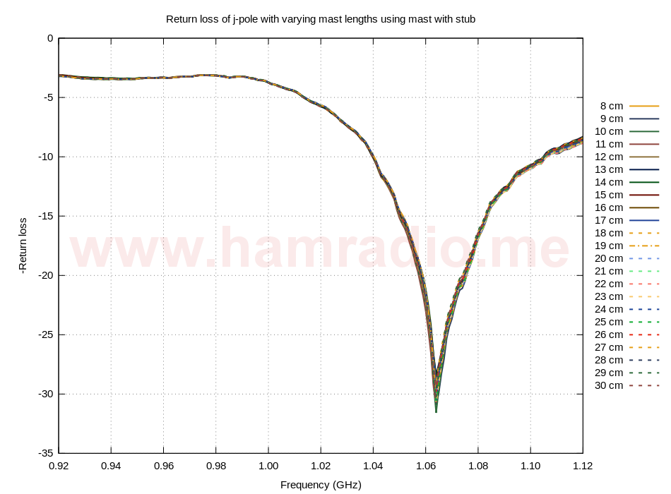
I’d say yes, wouldn’t you? The mast stub seems to have made the mast’s varying length invisible. It almost looks like fake data doesn’t it? I admit I did a double take when I first saw this graph, but it is real. We can view this return loss as SWR…
VSWR of J-Pole on varying lengths of mast with and without the stub
Whereas return loss provides sensitivity of small changes near the region of good matching, the VSWR measurements in figures 8 and 9 give us clues where the match is less optimal.
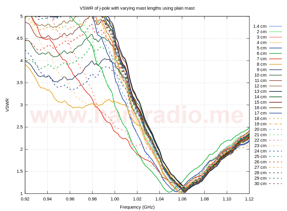
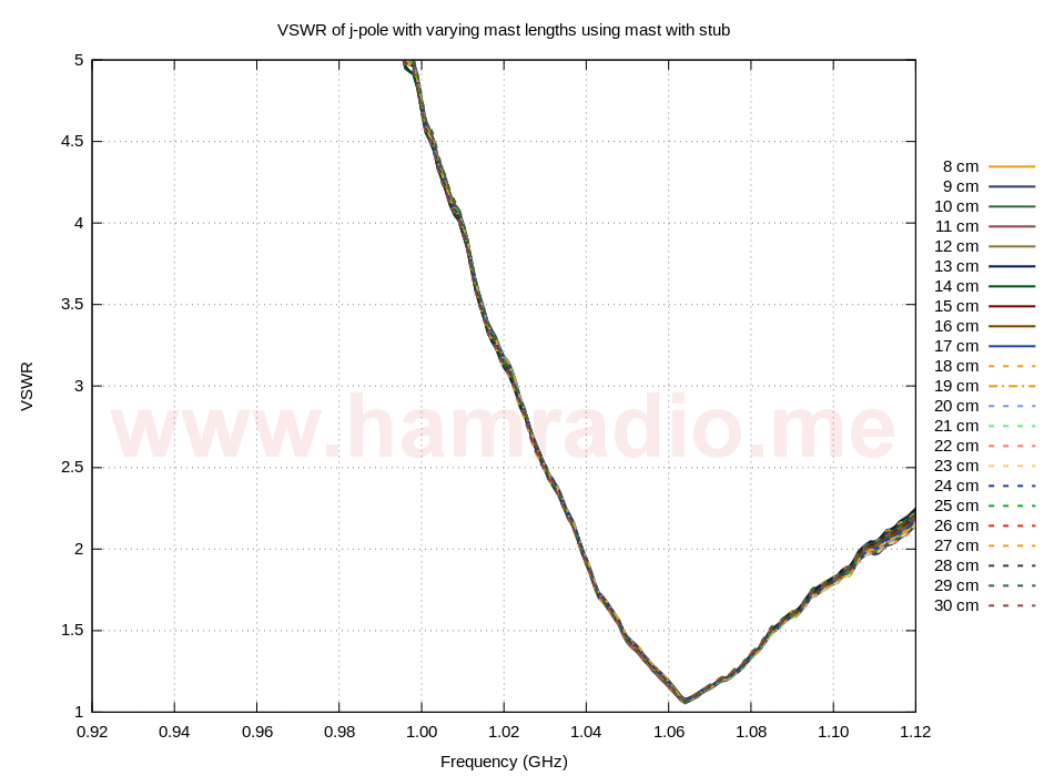
Once again we can see how the mast’s effects are visible with an SWR meter in figure 8 and are much less so in figure 9 with the addition of the collinear stub. The above two tests are similar to the “hand test” where you run your hand along the feedline and/or the mast to see if you can detect this on your VNA or SWR meter. The VNA is usually far more sensitive for this to work well, but don’t be put off trying the “hand test” with your SWR meter. Try frequencies just above or below as well. Plus don’t forget to move your hand at least a half-wave along the mast or feedline under test so you can be sure to hit both high current and high voltage points. Now it’s time to see some actual antenna patterns. Remember these are “real patterns” so you simulation deniers can just cool it and enjoy some real data.
Pattern measurements of J-Pole on varying lengths of mast with and without the stub
The gain plots of figures 10 and 11 have the shorter element of the J on the left and show the classic j-pole slight-loft of the lobe in the direction of this element.
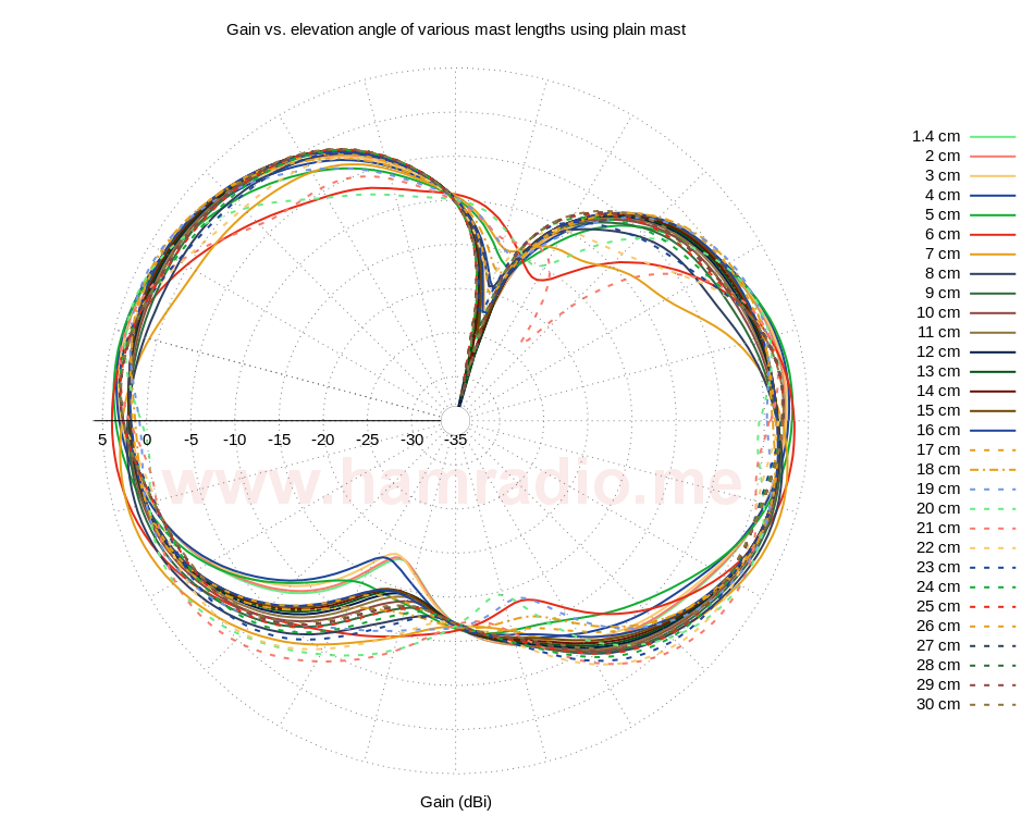
This antenna tends to hold its pattern despite the effects of the mast. Such might not be the case if the mast were longer, but I only had so much room to work with. The point is, changes to the pattern are clearly visible. Let’s see if the mast stub can help…
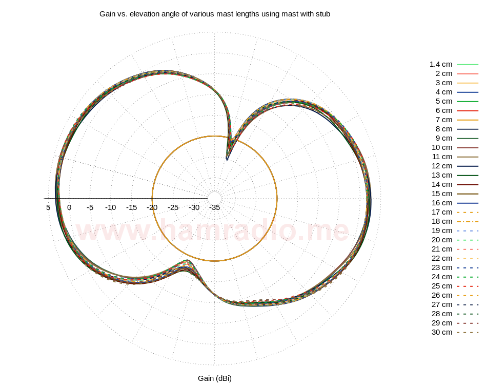
Note, in figure 11, the non-existent gain plots for mast lengths shorter than the mast stub were simply set to -20 dBi to account for them, but get them out of the way. Once again we see the stub doing a very good job of stabilizing the antenna to the mast’s influence.
Gain heatmap of above pattern measurements
Figures 12 and 13 plot the above gain data and mast length in a heat map to give us perspective how the pattern changes with subtle mast length differences.
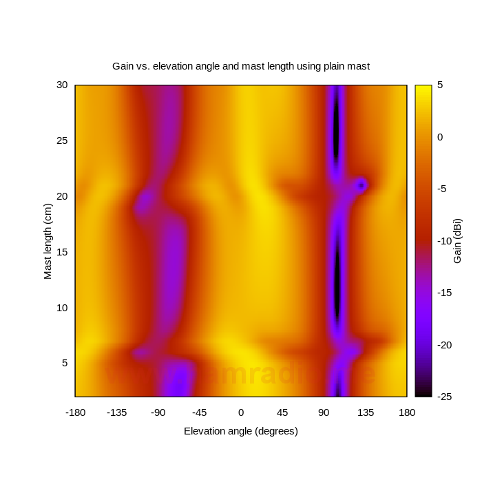
My favorite thing about figure 12 is the clear repetition every half-wave of mast length. Let’s now see how the collinear stub helps smooth the variations caused by the mast in figure 13…
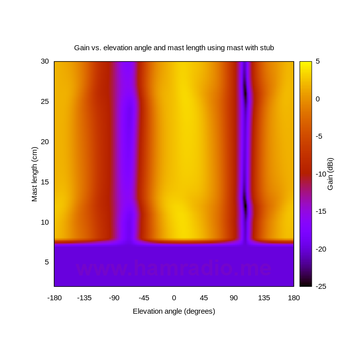
Once again the lengths shorter than the mast stub are normalized to keep the graphs the same dimensions. The improvement provided by the collinear mast stub to a j-pole’s operation is obvious.
Conclusions
NEC geeks are right The j-pole antenna clearly will flow currents to everything it connects with depending on the impedance, Zm, it presents to the bottom of the J. These actual measurements vindicate the NEC geeks’ alarms about mast and/or feed currents. The data shows a typical j-pole antenna does absolutely nothing to mitigate currents on its conductive mast.
Have your J-Pole and ground it too The above data not only confirms the problem with mast currents, but confirms a theorized solution with strong potential. The simple mast stub fulfills its simulation promise to help make the mast “vanish” to RF currents and no longer corrupt the operation of the j-pole antenna while still providing a solid path for lower frequency lightning surge currents. Other choke solutions will likely produce similar results.
NEC Faith now NEC Truth I admit the addition of the mast in the above test j-pole antenna never perturbs the operation enough to render the antenna inoperative, but do we really want an antenna this non-optimal? If we can now believe NEC helps us understand how j-pole masts become part of the antenna, we can explore situations where the mast is very long. Does anyone really want a “long wire” attached to their VHF antenna?
Stub that mast! It is likely time for a new round of j-pole antenna designs to incorporate the stub or perhaps an even better way to counter the obvious currents flowing on the mast. We all know to choke the feedline of a j-pole right? Is the mast really any different? By the way, this mast stub solution doesn’t apply to ungrounded j-poles so no worries about twinlead and other portable Js you hang from trees. For these just choke the feedline and operate.
Epilogue
The above test has been a long time coming. For years I’ve seen all kinds of web sites repeat the same old magical fiction about j-pole antennas not forcing currents down their masts by some mystical decree. Some merely repeat what they read in blind trust. Other more venerable sources, who should know better, maintain the fantasy. Most know just enough electro-magnetics to fool themselves apparently. It’s time for this to end don’t you think? My test and solution above are repeatable for anyone who desires to confirm the results.


Nice text. Please give us a short design advice on a J-Pole / Slim Jim Antenna.
Great article and well written. How might I ask Mr. Huggins a few questions I wonder?
Ask right here.
what an excellent artical backed be experimental evidence.. What a breath of fresh air… Thank you very much.