Hmmm…
Have you ever wondered…

…if shields change ferrite choking effectiveness? Image from Wikepedia.
Answer
Once upon a time I did wonder, but know better these days. However, the question is perfectly valid for those new to antennas and the methods of feeding them. The test to check on the behavior is easy to perform…. so testing we did… being Magnum Experimentum and all.
S21 in the open
Those familiar with S21 understand it is nothing more than attenuation (or gain) from point A to point B. Most instruments that measure this parameter seek to understand the losses associated with coaxial cables in differential mode. However common-mode power-flow eludes the typical S21 tests. We need to split the center conductor from the shield in order to assess the performance of common mode choking devices.
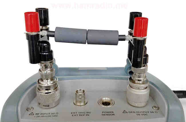
Banana plugs and lower test frequency to the rescue
One hundred uses for banana adapters… now one hundred and one. The photo below is the test setup from a previous article concerning ferrite testing.
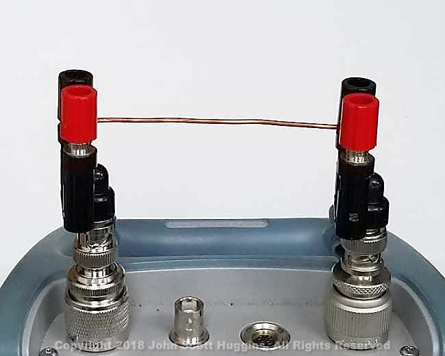
By applying limits to the maximum frequency, a successful test is possible so long as the deviation from 50 ohm coax seen above is relatively short vs. radio wavelength.
The copper wire shunting the shield posts (black) is somewhat redundant with the connection between the N connectors within the instrument. With this in mind, the tests for this article omitted this wire. This leaves only the conductor we place between the red posts. S21 sends energy out of one N connector to the red post and measures the power going into the other side. With calibration we can perform A/B comparisons of various configurations.
Conductors to place between the red posts
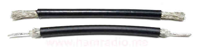
The two wires above were used in these tests with and without ferrites. The top is simply the shield of RG-58 coaxial cable. A piece of brass pipe or copper wire of similar diameter behaves the same, but this works well. The bottom is another piece of RG-58 with trimming to establish current only through the center conductor leaving the shield unconnected to anything, but still surrounding the center conductor.
A couple of Type 61 cylindrical ferrites from, you guessed it, Fair-Rite, fit perfectly on RG-58.
Calibrator
The top piece of RG-58 above was connected across the red posts and the analyzer was calibrated to this to give us our base line for all graphs in this article.
Various photos of the test
Not every test configuration is shown, but the following few photos highlight a few configurations. For each conductor three tests were performed with none, one and two ferrites inline.
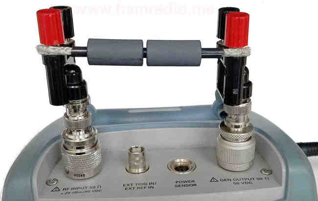
Close in look on the center conductor connection
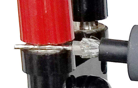
With care I ensured only the center conductor touched the red posts at each end while the shield remained floating.
Results with one ferrite

Key observations:
- The shield only configuration with no ferrites is a nice flat line since we calibrated the instrument to this arrangement.
- The center conductor S21 test shows a slight loss as frequency increases. Typical behavior for a smaller diameter conductor compared to our fatter reference.
- With one ferrite in place we see a modest, but usable, attenuation of the signal in this 50 ohm system.
- Most important of all, the shield has negligible effect on the choking ability of the ferrite.
Results with two ferrites

Adding another ferrite in series increases the total attenuation in this 50 ohm system. Once again we see negligible effect of the shield on choking attenuation provided by the ferrite.
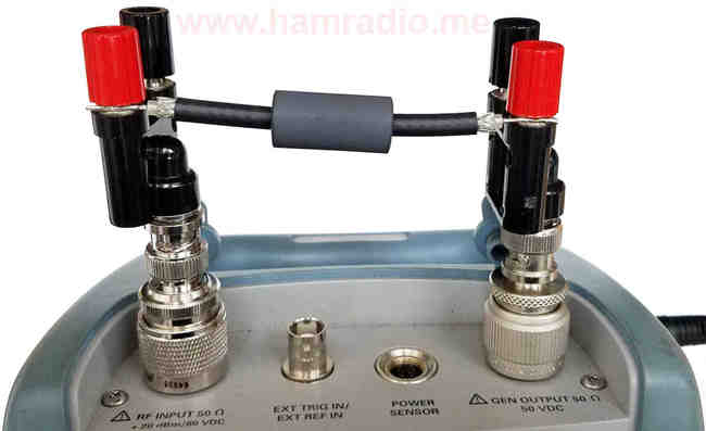
What if we connect one or both ends of the shield?
Continuing the experiment, I fashioned bits of brass wire to the black posts and bent into shapes that can swing in to connect to the shield to the analyzer’s connector “ground.”

The right banana adapter is the RF tracking generator output, the left the RF input. In the above photo we have the example with the shield tied to the RF input side. I measured all four possible scenarios of these two shunt-wire variables through a single Type 61 ferrite.

 The cases when one or no shield ends connect results in the ferrite still performing an RF choking action. The higher frequencies diverge a bit most likely due to random capacitances doing their thing.
With both shields connected we merely have a poorly connected piece of coax operating in differential mode. This, of course, slips past the ferrite as we expect. The line drifts upwards with higher frequency merely because the analyzer is still calibrated to the “Shield Only” reference in the previous graphs. When and where to normalize data sets is an OCD Nightmare. For this article, all graphs are normalized to the same reference…
…except for the following graph normalized to the “Both shields connected case”…

Conclusion
Common mode current is the net sum of all currents flowing inside a choking ferrite no matter if inside or outside the conductive shield of the coaxial transmission line. Or at least that’s the effective result. Some will logically argue the currents inside the coax must be equal and opposite (at RF) regardless of how they are hooked up suggesting the current on only the outside is common mode and effected by the ferrite. How to view this is a good question. The major point is, for whatever reason, the choke chokes as if the shield isn’t present.

Can you say a bit more about the calibration procedure?i am using a nano VNA which so far I have only used in s11 mode.
The open test is obvious, but in testing short and load, where do you place a short circuit and the load?