The Zed challenge – next step
I continue to gear up for the challenge from AI3V…
I followed the same basic approach of creating a completely wireless (except for the antenna of course) test transmitter. Essentially another Pi Zero was put to work as a near-field measuring device with wireless connectivity to an operator via the WiFi of the Pi.
Here is what I’ve come up with…
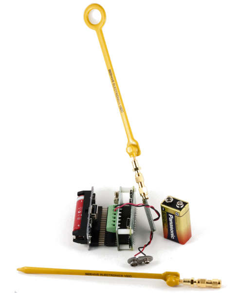
Seen is professional grade probes next to a Raspberry Pi stack with built in power source and A/D converter. An rf to voltage converter board on the probe is unfortunately edge-on in this photo, but more details are below. The 9V battery powers the rf to voltage converter. More details below.
Let’s examine the steps taken.
Measure fields rather than currents
Our goal for this test is to see if an rf source can energize a dipole antenna the same whether fed in the center or the end. Measuring the current is certainly a good way to do this, but an important premise of this effort is to not disturb the antenna under test (AUT) as much as possible. There are lots of low intrusion devices to measure the rf current along a wire, but all of them introduce at least a little “change” to the antenna system. I prefer an indirect way to measure antenna energy and there are ways to accomplish this.
A dipole generates both electric and magnetic fields of consistent amplitude for consistent power applied. Therefore if we can measure the fields near, but too near, the antenna wire, we can minimize interactions of the measurement gear with the antenna. Of course we need to do this with conductors much much shorter than the wavelengths under test. Hence any sensors need to be very short with respect to wavelength.
Real field sensors
Plenty of homebrew approaches exist to measure E and H fields. I wanted some pedigree with these measurements so opted to purchase professional grade sensors. A quick search on the Internet led me to Beehive Electronics where I purchased the whole set of three H and one E field probes.
Here is a photo of the largest H field (Model 100C) and the only E field (Model 100D) probe as received. The H field probe is the one with the loop.
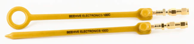
Annoyingly, these probes come with the rather rare SMB connector. Further investigation suggests this is the norm in the EM probe world so I simply purchased some adapters from Amazon to convert to SMA.
The data sheets for these probes include formulas to convert power delivered into 50 ohms into the resulting field magnitude. Like I said… pedigree.
One nice feature that confirmed probe functionality is the orientation of the H field loop with respect to the current carrying conductor matters… as it should. This suggests the probe does indeed reject unwanted energy and focuses only on magnetic fields. The E field probe by comparison is insensitive to orientation. W2AEW explains and demonstrates…
Signal flow
Assuming we can hang these probes near the AUT, we will receive an rf signal with amplitude proportional to the field being measured. So what’s next? I came up with these steps…
- Use H or E field probe to convert fields to rf signal.
- Use RF to Voltage converter to translate this to a dc voltage.
- Use voltage to digital converter to translate to digital form.
- Use microcontroller/processor to relay digital information to data recorder wirelessly.
After some research and tips from Andy (K1RA), the above list translates to…
- E and H probes from Beehive Electronics (see above).
- AD8318 RF Logarithmic Detector RSSI Measurement Power Meter 1-8000MHz 70dB – see Amazon.
- Seeed Studio 4-Channel 16-Bit Analog-to-Digital Converter(ADC) – see Amazon.
- Raspberry Pi Zero W (I just buy the CanaKit) – see Amazon.
- Raspberry Pi Li-ion Battery HAT 5V Regulated Output – Self contain power source for Pi Zero – see Amazon.
- Some Li-Ion batteries from Amazon (I can no longer find these, but they have to be out there somewhere). Note regular AA batteries will not work.
Closer look
The next photo shows everything less the Beehive probe.
The 9V battery supplies the 7-12 volts required by the RF detector board. Otherwise I would have tapped the power from the Li Ion, but this is all still quite compact and just fine for the short test runs I will need.
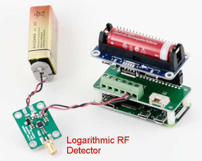
The RF detector produces a voltage inverse to the RF energy received so this has to be taken into account during analysis. The data for the AD8318 has all the details. I personally measured mine in a laboratory environment and created the conversion math from these measurements.
The Pi Stack
This photo gives details on the Pi Zero stack. Note the stacking header alleviates the issue from the tall terminal connector on the A/D.
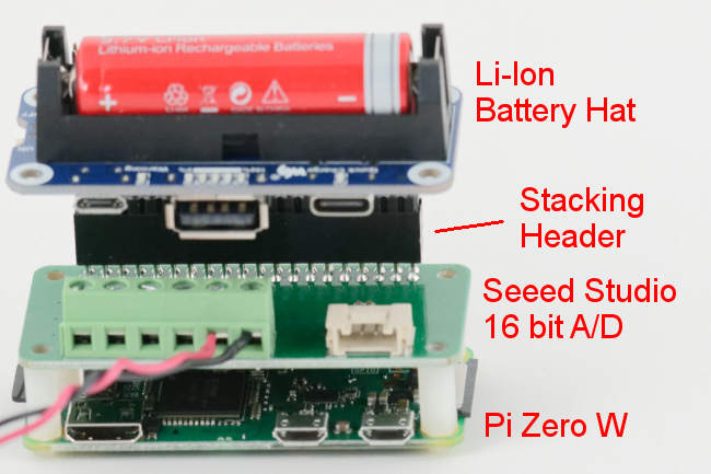
The Pi Zero “W” has built-in WiFi antennas that seem to work surprisingly well. The Seeed Studio A/D takes a lot of steps to make it work, but it is all very straight forward.
Conclusion
Preliminary tests of the above system with a shell into the Pi and with an HT to energize the probe confirm response to H-field energy when the loop is in the plane of the aerial and no response when orthogonal. The E-field sensor properly identifies the higher voltage at the tip of the antenna. All that’s left to do now is put together a 30m dipole with options for center and end feeding.
Some packaging issues remain along with concerns how the electronics will function near an antenna with less than a watt of test power flooding the immediate area with approximate 10 MHz electromagnetic energy.