Once upon a time our local ARA organized a show and tell session at a monthly meeting. One fellow brought in a piece of aluminum extrusion square tube with N connectors outside and a round brass tube within. It was a four way RF power splitter for his 0.23 cm yagi-uda array.
1973
Later research led me to this copy of a 1973 QST article…
http://home.teleport.com/~oldaker/power_dividers.htm
The basis for these designs is the quarter-wave transmission-line impedance transformer. Several styles are described in the article. The one-to-four splitter caught my eye…
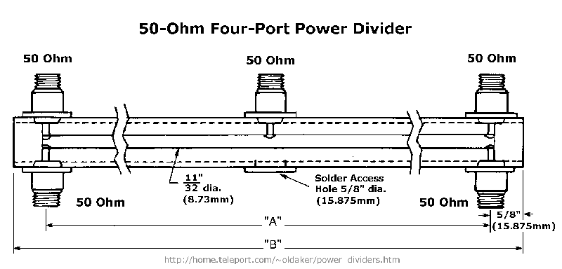
Here we have a device made with 1 inch square aluminum tube with 1/8 inch wall thickness. Inside the 11/32 inch round brass tube yields a characteristic surge impedance close to 50 ohms. At first glance one might wonder how this arrangement yields a one to four 50 ohm splitter. A builder selects dimension A to be 1/2 wavelength of the desired frequency of operation. This results in two quarter-wave coaxial transformers: one from the center connector towards the left, the other towards the right. A coaxial version is another popular way to make a four port splitter using just 50 ohm coax and three connector Tees.
Let’s study the impedance transformations starting on the left.
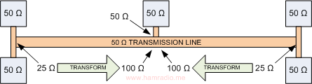
Steps:
- We start with two pairs of 50 ohm ports;
- Each pair in parallel gives us 25 ohms;
- We use two 50 ohm quarter-wave sections of transmission line to transform each 25 ohm impedance on the ends to 100 ohms in the middle;
- Two 100 ohm impedances in parallel combine to 50 ohms at the center connector;
This is how you build a four way splitter with just 50 ohm coax and some T connectors. Here we build the same thing, but with aluminum and brass for a sturdy assembly.
A tale of two UHF power splitters
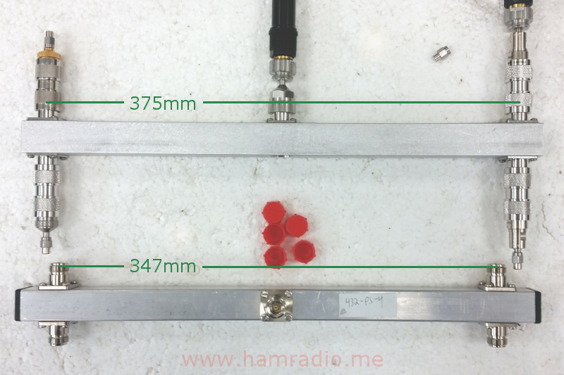
Wanting to investigate the aluminum power splitter approach, I sampled two units. One is a 432 MHz model from InnovAntennas. The other is one I built by hand interpolated to 400 MHz. Both are based or derived from the dimensions of the 1973 article. In the case of the 432 MHz model, dimension A is 347 mm. A little math reveals this is simply the halfwave calculated from free-space speed of light – 300 m/s / 432 MHz / 2 = 0.347 meters or 347 mm. Using the 432 MHz and 347 mm as a baseline, I calculated dimension A for 400 MHz should be 375 mm.
The following picture shows both units ready for S11 and S21 testing.
Let the testing begin…
S11
The following S11 graph is of both splitters each loaded with four 50 ohm loads.
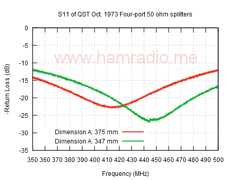
Both units measure 15 MHz higher than frequency goal
The 432 MHz splitter from InnovAntenna produces a deeper return loss than my 400 MHz version. Note the 432 MHz unit actually tunes in about 447 MHz. My 400 MHz version tunes in around 415 MHz. The bandwidth of both units is quite broad and useful at their original intended frequencies. However, I wondered if the original authors of the 1973 article actually measured their prototypes to arrive at the stated dimensions. Based on the two examples both being too high by the same 15 MHz or so, I conclude they didn’t have the test gear required to nail the design frequency. It may not have mattered much as the S21, below, shows just over 6 dB down on the split ports over a considerable frequency range.
S21
The next graph shows the S21 between the common port and one of the four splitter ports.

Both units exhibit a nice broad frequency range.
Still one wonders why the consistent difference. This is an air dielectric transmission line. If dielectric effects were to creep in somehow, one would expect the quarter-wave transformers to electrically lengthen and lower the frequency. The frequency of our two examples went up. Hmm.
Thoughts
One clear way a real transmission line can have different propagation speed is dielectric loading. Everyone knows dielectric filled transmission lines have velocity factors less than unity. However, that only electrically lengthens the line such that a, say, quarter-wave stub cut to free space dimensions resonates at a lower frequency, not higher. Plus our aluminum transmission line is very close to having an air dielectric. It’s no surprise the authors of the 1973 article chose to use free-space wavelength calculations in their air filled transmission line. Indeed, their 432 MHz dimensions got close enough for the units to perform their intended role even if not spot on the target frequency.
Conclusion
The moral of the story appears to be the original authors were off a bit on their length calculations, but only testing with laboratory grade gear would have revealed the difference. I only tested units near 400 MHz and can say with some certainty the frequencies will be 15 MHz higher using the 1973 recipe as a guide. The 1973 authors can be excused for not having access to today’s modern VNAs. InnovAntennas are obviously just following the 1973 recipe and selling it with no laboratory testing. Fortunately the bandwidth is broad enough to cover the 432 MHz target frequency. The InnovAntennas 432 MHz splitter is perfect for 440-450 MHz projects.
It’s clear the dimensions shown in the 1973 article need some adjustment to yield their promised center frequencies. In the case of 432 MHz, dimension A should likely be changed from 347 mm to 360 mm. The reasons why this is so remain a mystery.


