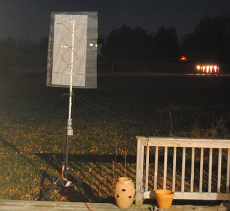
The Doyt Hoverman UHF TV Antenna
I found an opportunity to measure the performance of this Hoverman TV antenna…
…built from details found on my previous DTV Antenna article.
Hoverman with a Screen
The typical Hoverman design uses tuned rods as the reflector medium. I followed the guidance of some builders who use a simple screen reflector instead of the more complicated rods. Some use two vertical screens side by side instead of one. These suggestions and my simulations suggest unplanned VHF performance might be possible with the simple large single reflector screen. Since two local stations still broadcast on their RF channels 7 and 9, this is how I built my antenna.
The resulting antenna assembly provides very good UHF performance picking up stations over 40 miles away with ease and doing so with the mid point of the antenna only 8 feet above ground. One station is at the relatively high channel 48 which this antenna does detect. A pleasant surprise is the sensitivity and directionality of the two VHF stations. I thought I might be able to detect VHF, but didn’t expect the narrow beamwidth.
Let’s examine the antenna in a test setting showing the real azimuth and elevation patterns.
Hoverman Antenna UHF Performance
The following two graphs show the performance of the Hoverman Screen antenna at three UHF frequencies representing the almost the entire range of today’s UHF TV band – Channels 14 – 51.
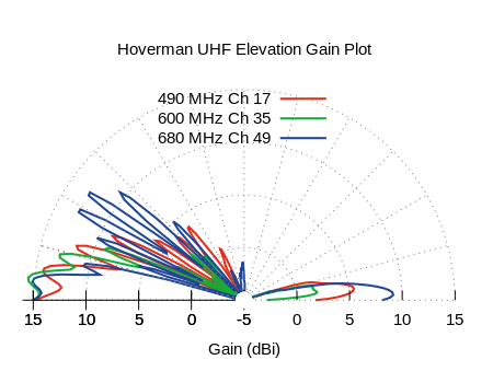
The takeoff angle is wavelength dependent of course and there isn’t a whole lot you can do to change this except adjust the antenna height. Figure 1 does reveal how well the 2×2 collinear structure of Hoverman’s approach controls the vertical spread of energy. There is no doubt the pattern hugs the horizon quite well despite a few narrow high-angle lobes at the highest frequencies.
Figure 2 shows the azimuth patterns of the same three frequencies at their optimum elevation angles.
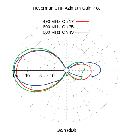
This antenna topology provides good gain and beam shape over nearly a 2 to 1 frequency range.
I noted how sloppily my sons and I built the antenna in my first article about this antenna. You can see the results in Figure 2. The screen reflector is not perfectly flat and is a little bent on one side. The copper zigzag element is not perfectly symmetrical. That said, the antenna still gives quite adequate performance. With a little more attention to symmetry, there is no reason this design cannot be the ideal directional UHF HDTV antenna for anyone.
The original Hoverman patent antenna dimensions provide coverage of only part of the UHF band. The slightly shorter horizontal section in the zigzag element tips increase the range to cover today’s entire UHF television band. Thanks goes to the Canadian NEC Geeks for figuring this out.
Hoverman Antenna VHF Performance
We tested the VHF performance of this screen Hoverman as well not expecting much. To our surprise, the antenna has adequate, even superior, performance on the high-VHF band – channels 7 – 13. The following plots show the Hoverman at RF channels 7, 9 and 13.
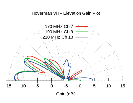
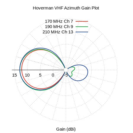
The full size screen behind the zigzag elements produces very good behavior in this TV band. Interestingly the performance on the frequencies above the VHF HI and below the UHF band (the actual design band) is quite poor. The fact it works at all on VHF HI is pure coincidence.
Needless to say this version of the Hoverman TV Antenna with screen rather than rods fulfills the requirements for a VHF and UHF TV antenna.
Hoverman Antenna with Screen Conclusions
The 1960 design of the Hoverman with a simple full-size screen reflector modification (replacing reflector rods) provides coverage of today’s UHF television band by design and the VHF HI television band by happenstance.
Needless to say, I’m done looking for a TV antenna. Oh I’ll likely improve the construction methods and materials over time, but the overall design of Hoverman’s zigzag element over a reflecting medium is rock solid. All our future TV antennas will be of the screen Hoverman design.
Thank you Doyt Hoverman for your timeless design.


John, I've made a couple prototype Gray-Hoverman antennas out of 8 ga copper wire. I've added a 31 inch NAROD to one in order to improve its VHF Hi performance. A future project may involve aluminum screen frame elements…
I am a retired TV chief and RF engineer and have a unique situation. I am surrounded by a cluster of 4 cell towers all less than half a mile away, plus a hospital with 200 watt ERP on 451 and 462 Mhz. only 1/2 mile away. and a TV studio with 460 Mhz and weather radar less than 1/4 mile away. I am also looking directly through 50,000 watts of FM and 5000 watts of AM about a mile away to see the TV towers about 20 miles away. TV Channels 57, 58, and 59 already have LTE data on them about 20 DB stronger than the local TV channels on the spectrum analyzer. Ch 47 and other LTEs are being built and I can see them sweeping the antennas. Can you say interference city? TV repack has already occurred here and the top TV channel in use is already channel 36. plus a VHF ch 7. A 54 Mhz. high pass got rid of the AM and all the CB and low band 2-way stuff plus an FM trap filter and a Channel Master LTE filter (low pass 700 Mhz.) solved the FM and LTE interference initially.. After repack I replaced the LTE filter with a 600 Mhz. LP filter – goodby AM, CB, FM and LTE crap.
I built the Gray Hoverman single bay antenna with a PVC frame using a split screen wire mesh reflector, mounted it in the attic and it was able to drive 5 televisions with no amplifier! I added 2 NARODS cut 1/2 wavelength for ch 7 and folded several inches on the ends to match the length of the Hoverman elements on the top and bottom spaced about 1/2 inch from the horizontal portion of the Hoverman elements. Negligible UHF change but great improvement on ch7. I was still having interference problems and discovered it was overdrive of the TV front ends when the 450 Mhz. Hospital and TV studio triggered their 2-ways. I decided to build another Hoverman close to the original design which was rated to TV ch 36 – perfect. I used a solid vinyl coated foil as a single reflector to help the ch 7 low level problem, used 7 inch Hoverman lengths throughout and spaced the 30" x 40" reflector 4 1/2 inches behind the driven element. This put the upper bandwidth near channel 36 and lowered the overall gain about a db or so over the split screen plus increased the gain on channel 7. I am now enjoying interference free TV on actual ch7 through 36 and have 19 local digital channels. This was a real challenge.
This is what is so great about being able to get down to earth information at one's fingertips. Job well done Sir. Please keep us all in the loop. V