Ahh… the J-Pole Antenna…
The J-Pole antenna, more properly known as the J antenna [6], is one of the most popular antennas for 2m vertical use in the amateur radio ranks. It has been around for many decades [1]. I have covered J-Poles quite a bit on this site [2]. My favorite feature is the versatile feed adjustment provided by the J part of the antenna.
A great many web sites and antenna books provide construction details. More site authors, including the late L. B. Cebik (W4RNL SK), try to understand how the J-Pole works with extensive simulation using NEC [3].
The Traditionalists’ Message
A surprising number of authoritative sources swear the J-Pole antenna works perfectly with full connection to other conductors alleging zero voltage potential will ensure no RF current flows through the base of the J and into the supporting structure.
The following comment from a forums.qrz.com thread titled “J pole Ground questions” typifies this understanding…
“Normally, everything ‘below’ the shorting bar at the base of the antenna [. . .] can be grounded since everything below that point is not part of the antenna and carries no RF current.“
The conductor below the J is not part of the antenna???
The NEC Geeks Sound the Alarm
The alert from the NEC crowd (since at least 1998 [5]) is how the J-Pole antenna behaves when the bottom of the J has a direct connection to other conductive structures. Many novice antenna enthusiasts, like the poster above, assume the bottom of the J in the J-Pole is at such potential to not conduct RF to anywhere, except the upper radiator. The NEC simulation folks provide the opposing view the bottom of the J-Pole antenna is very sensitive to additional conductors that have just as much right to the RF current as the upper radiator.
Obvious points include:
- Zero voltage means Zero current which means Zero power which means nothing happens?!?!
- The bottom of the J is the midpoint of a half-wave section bent into a U. Voltage is indeed at a minimum, but current is maximum… not zero.
- Where the bottom of the J meets the “traditional” conductive mast a three way connection exists.
- Where a three way connection exists, Kirchhoff’s Law [4] prevails… at least for distances much much smaller than an electrical wavelength which is the case here.
Kirchhoff says…
No matter how a J-Pole is fed, RF currents must pass through this three way junction. Both the upper half-wave of the J-Pole antenna and the mast compete for RF current based on the impedance they present to this junction. There is nothing magical or mystical that makes the J-Pole immune to these basic engineering facts.
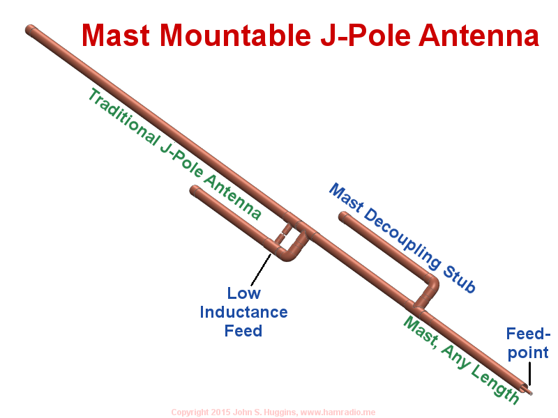
The next figure highlights how attaching the J-Pole to a mast brings in the impedance of the mast resulting in a three way current node composed of impedances Za (upper element), Zs (stub) and Zm (mast); The impedance of the source is part of this too, of course, but you get the idea.
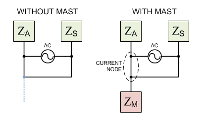
The impedance of the mast has just as much right to the current as other paths. The ratios of the mast’s RF current depends on the ratios of all impedances. Can we calculate these currents? Yes, we can, but it is easier to simulate with NEC or other simulation methods.
The video below shows a time based simulation of a 2m J-pole atop a one wave-length mast with a direct connection to ground. The full wave-length mast represents a worst case scenario where the ground’s low impedance appears as a low impedance at the three way junction… much like any multiple half-wave-length transmission line.
Press play to see a 146 MHz sine wave at the bottom of the J ramp up to full intensity, sending currents through the structure and eventually reflecting currents from ground and the top of the antenna to create the standing waves that make antennas work. What you see in the video is the amplitude of the H field around the antenna; These are proportional to the current in the conductors and give the viewer a good idea where RF currents flow.
Hurl.
In this circumstance, the mast becomes as much part of the antenna as the J-Pole. The J-Pole antenna is merely a coupler inducing RF currents in every structure: radiator AND the mast. Not good.
So the NEC folks’ warnings are valid.
What if the mast is a “quarter wave transformer?”
If the grounded mast is an odd number of 1/4 waves long (1/4, 3/4, 5/4, etc.) then the impedance of the mast at the three way junction is higher than the upper portion and, thus, less current flows into the mast. So, sure, it is possible to reduce the mast currents through judicious calculations and experimentation. However, any antenna design so sensitive to the structure it sits on is a poor design. This assumption holds true only for a straight mast. A tower with lattice structure is likely a mix of “distances” to ground so getting the mast to present a high impedance to the three way junction is a matter of pure chance.
The above 1 and 3/4 wave-length mast discussions assume the bottom of the mast connects to a good RF ground. The behavior reverses if the bottom is an RF open circuit… just like with transmission line transformers, stubs, etc.
The point is any antenna that needs so many things to be “just absolutely right” to work well, is hopelessly ridiculous. It’s better to give the antenna a fighting chance by “electrically floating” it from its mount.
The J-Pole Antenna ‘Drinks Alone’
The J-Pole antenna must have electrical “RF” isolation from its mount to maintain its design goals. This is most easily accomplished when the mast is made of insulating material. If one desires a DC ground, with the goal of keeping the mast impedance Zm high we have some choices including:
- Position a non-inductive resistor across a non-conductive portion of the mast if your concern is bleeding static charge from the antenna.
- Install an inductive choke across a non-conductive portion of the mast which blocks the RF, and passes DC.
- Use a fully conductive mast with two more more horizontal radials 1/4 wavelength below the base of the J.
- Use a fully conductive mast with collinear choke connecting to the mast at its bottom about 1/4 wave beneath the bottom of the J and facing upward. The open end of the collinear choke is just below the J.
All these choices help maximize the mast impedance Zm and reduce currents on the mast. The latter two preserve a very low resistance path for DC currents. All preserve the J-Pole’s natural antenna pattern. An explanation why will be in an upcoming post. Note the plain J-Pole antenna has no need for the above treatments as the many other posts on this site verify[2]. It is only the addition of the mast that requires mitigation techniques.
The Luddites Say…”We don’t need no stinkin’ [electrical] rules.”
Why have such basic electrical rules been ignored over the many decades this antenna has been with the ham community? My best guess is hams typically only look at the SWR of the antenna and observe whether it gets out. If their J-Pole antenna is electrically attached to their tower, mast or whatever, they are likely “loading up” the whole thing as a radiator with unpredictable and bizarre antenna patterns. Let’s face it though… bizarre patterns often still work and get the job done. Thus, bad antenna behavior goes unnoticed.
Mast currents from J-poles are not a recent discovery. A thorough explanation is found in the March 1998 issue of CQ Magazine. The author’s summary says it all.
“Mounting a J-pole directly to a conductive mast and feeding the antenna with coax without some method of preventing or reducing common mode current on the transmission line will result in producing a high proportion of the signal being wasted at high take-off angles. For better ground-wave communication a J-pole should be isolated from any conductive supporting structures and a method of eliminating or greatly reducing the common mode current on a coax transmission line is required.”[5]
The above quote concludes an excellent in depth article about why and how to electrically isolate the J-Pole. It is a must read for anyone desiring to build a J-Pole antenna.
Actual Testing (update February 2015)
I finally got around to testing the j-pole with real instrumentation and a real far-field gain measurement. I confirm the mast’s propensity to draw current from the j-pole bottom and, using one of the solutions proposed above, confirm a way to mitigate it while still maintaining a dc path to ground. Read all about it here…
J-Pole Mast Current Measurements
J-Pole Antennas are still Cool
Fret not J-Pole lovers. While not found often in commercial environments, the J-Pole still has a place. Collinear Super-Js work pretty well and are cheap to build. The J-Pole’s adjustable feed-point makes it easy to match choked or baluned feed-line to the antenna… assuming the J-Pole resonates correctly of course.
With the electrical isolation requirement, the traditional cooper cactus design needs modification. Unfortunately this makes the assembly a bit less sturdy. However, this is where ingenuity from the ham community shines.
More folks are realizing the pitfalls of direct grounding the J-Pole. In time, new clever solutions to properly isolate the J-Pole from its mount will become the new normal.
References:
- Rogers, G.E. (K4ABT). “J-Poles Handbook, 4th Edition.” 2011.
- Huggins, John (KX4O). “J-Pole Posts on Hamradio.me“
- Cebik, L.B. (W4RNL). “Some J-Poles that I have Known” – www.cebik.com: 2008.
- Wikipedia. – “Kirchhoff’s Law“
- Richardson, Dan (K6MHE). “The J-Pole Revisited.” CQ Magazine: pp 34-41. March 1998.
- Antennas and Antenna Systems (TM 110314). U.S. War Department. 1943.
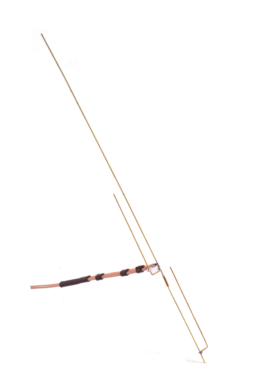
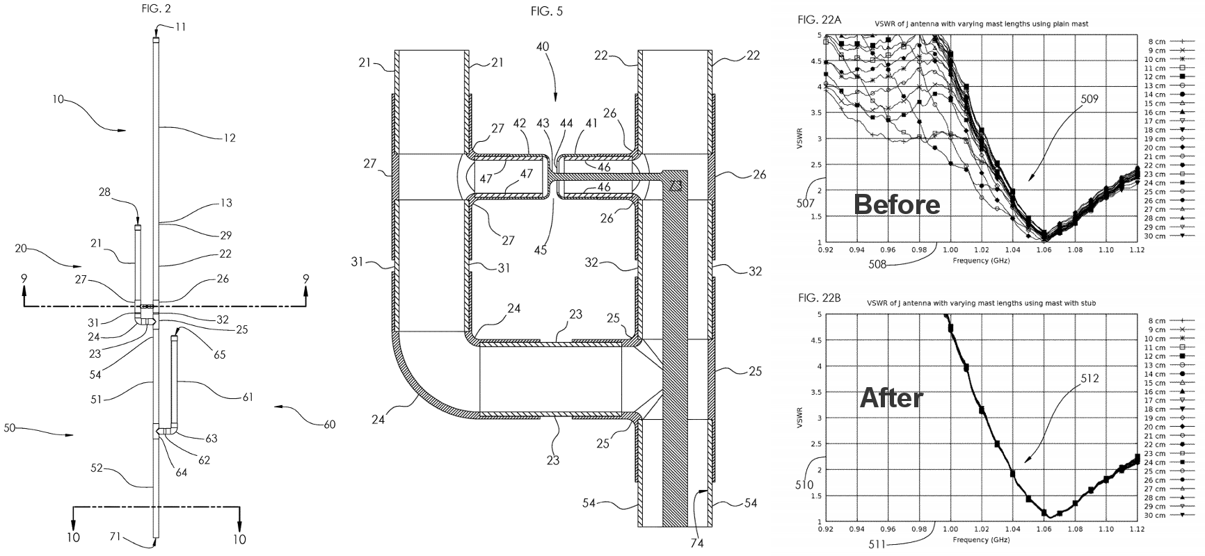
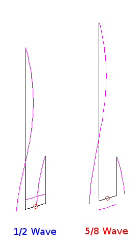
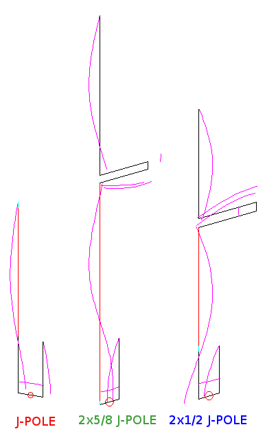
Wes Hardaker posted some SWR measurements of his Super-J with and without a ground wire and feedline choke…
http://pontifications.hardakers.net/amateur-radio…
His measurements support the notion the J-pole couples currents to anything connecting to it including conductive mount structures and ground wires
Performing the "hand" test on the ground wire would likely change the SWR as well.
Good stuff. Thanks.
Great article, consequently I constructed my j-pole isolated from the mast. Just wondering if the metallic mast itself should be earthed, even though it is isolated from the antenna, could it induce interference in the antenna? The j-pole is mounted on top of the mast and isolated with a plastic connector.
I've been examining this very issue for a presentation I'm giving to a ham group this Thursday on J-Poles. One of the things I've found is the radials on a standard monopole antenna actively couple energy to the mast below even if the mast is electrically isolated from the antenna. The slender nature of the J-Pole reduces this particular coupling quite a bit.
Whatever coupling there is from J to mast would setup currents differently depending on mast length and what's at the other end: ground or isolation. A good default would be to ground the mast for safety's sake.
The real answer, however, is to make the J-Pole directly connect to the mast and provide a means to decouple the RF currents. I think I have a reasonable way to do this and will post the results after the presentation.
Results are posted… http://www.hamradio.me/antennas/j-pole-antenna-gr…
Stupid antenna anyway… thousands of stray RF generators proudly exclaimed as a great antenna with no freaking knowledge about any of it.
With certain embellishments, the j-pole has hope…
http://www.hamradio.me/antennas/j-pole-antenna-gr…
Bought a commercially made 2/70 J pole which was dead cheap, common sense told me to isolate this from the mast just like you would not allow an antenna to touch another piece of conducting materiel, I used a modified plastic bottle as a shief followed by an air choke ( standard) hey presto, works as good if not better then my more expensive colinear vertical I had up previously. Only spoke to two local chaps and was pushing them hard over, but was opening the 2m repeater some 40 miles away on 10 watts. Im quite pleased so far and plan on putting it even higher then the present 35ft. For under £30 British pounds it seems worth every penny. Joe. 2E0SIR.
Why would some one pay good money for an antenna that's been scientifically designed using electrically and mechanical properties for a specific frequency then change this concept and design feature by adding a further conducting length of material to it. Isolating the antenna from the support mast makes perfect sense to me.
Would you buy an aerodynamic sports car and then weld a steel gate to the front bumper changing its overall purpose.
Electrically isolating the antenna from the support structure makes good sense, Some, however, like the idea of the antenna having some sort of continuity to ground via the structure. With that in mind the only remaining question is if this continuity needs to be a low current bleed or something more stout for lightning surge handling. An RF choke handles the former and a mast decoupling stub handles the later.
I was wanting to make an aluminum J-Pole similar to the Arrow design as a project for my 11-year old son and I. Would I ground it or protect it from lightning after I mounted it to the roof?
I have a conventional 2m J Pole, and the mast I set it up on is a PVC pipe capped at both ends and internally supported with 1/2 inch rebar. Since this is a non conductive mast, are the currents mentioned above as mast currents really a significant factor in the performance of the antenna? I also note several persons have asked for dimensions and they were expressed as wavelength fractions. Could you provide us with the real dimensions of your example so we can get a real world idea of the materials and the finished product's size? A 6 meter conventional J Pole made from copper pipe is over 13 feet long. It would be great if we knew how long the antenna and it's stubs are in physical measurement.
Whatever coupling there is from J to mast would setup currents differently depending on mast length and what's at the other end: ground or isolation. A good default would be to ground the mast for safety's sake. I used a modified plastic bottle as a shief followed by an air choke hey presto, works as good if not better then my more expensive colinear vertical I had up previously.
Uso uma jpole feita por mim,construí umas 100 dessas ,tanto de aluno e cobre,já usei aterrada e agora só uso Isolda do mastro,uso um Ht icv68 e essa antena j de tubo de alumínio,estremamente um roe perfeito 1:1.1 excelente antena ,falo numa distância de 30 km com 2w,melhor que isso , só duas j….73