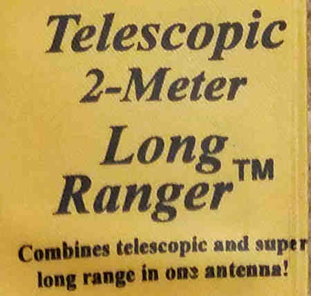
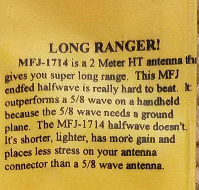
The MFJ-1714 has “Super Long Range” baby! Now that’s confidence in advertising for a simple concentric sleeve, bright and shiny, collapsable antenna. The packaging exudes even more confidence with the following knee slappers…
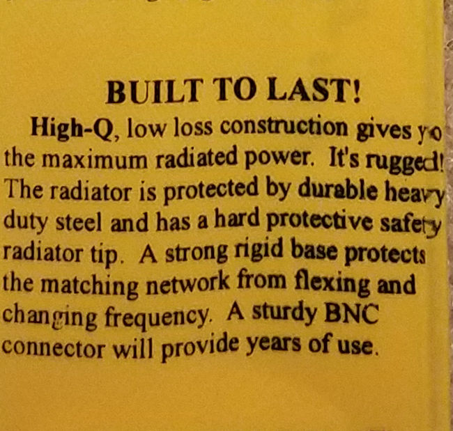
Built to last how long?
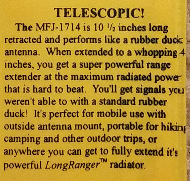
Ah… super powerful range extended.
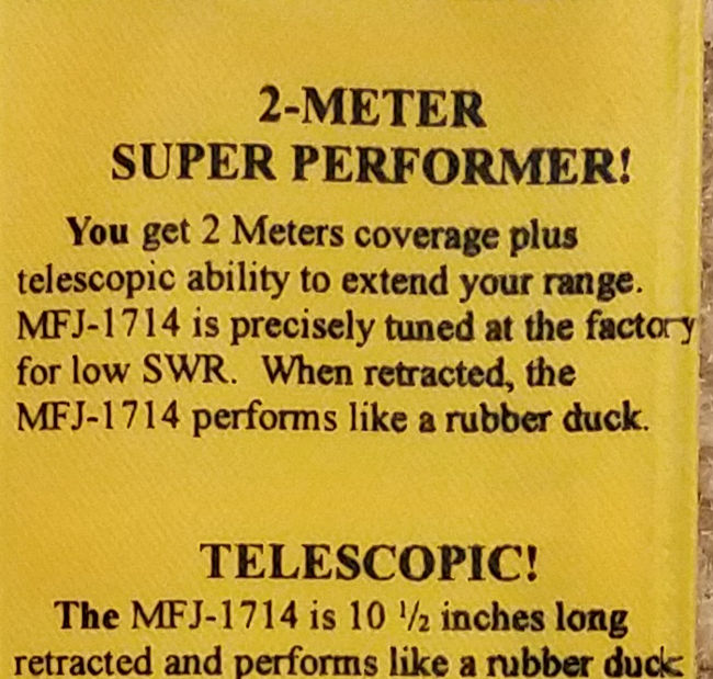
Telescopic ability to extend your range?
The “Long Ranger… really hard to beat?
Click each to enlarge if the power of positive thought is your thing. When you are done continue reading for some real analysis of this antenna and how it helps us understand a dipole can effectively be energized from its end.
The MFJ-1714 half-wave antenna
This MFJ antenna features the above said telescoping section conductor paired with a functional high to low impedance transformer. A quick check with an ohm meter reveals the primary element has dc conductivity to the shield of the connector. It’s available with a BNC or SMA… perfect for most hand transceivers.
I originally thought the “1/2 W” on the MFJ site suggests the power limit of this thing is a paltry 1/2 watt since, well, “W” is the SI indicator for the watt. Thanks to an observant patron of this site, I now understand this is MFJ’s non-standard way to indicate 1/2 wavelength. Regardless the MFJ-1714 provides an excellent test piece to help us all understand how an end-fed half-wave antenna functions.
EFHW – Does it require adding counterpoise wire or not?
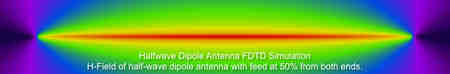
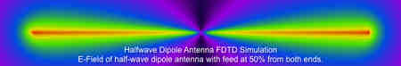
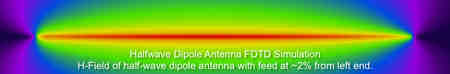
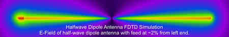
I discussed this quite a bit with the simulations (FDTD) in the article “Of Fields and Feedpoints.” Fitting perfectly fine with the definition of a dipole, you can, at least by definition, feed a half-wave dipole anywhere along its length and have a radiating structure. These E and H fields…
H-Field of half-wave dipole antenna with feed at 50% from both ends.E-Field of half-wave dipole antenna with feed at 50% from both ends.H-Field of half-wave dipole antenna with feed at ~2% from left end.E-Field of half-wave dipole antenna with feed at ~2% from left end.
…describe half-wave dipole action differing only in feedpoint placement… or so the simulations say. The key takeaway from these earlier sims is not that a counterpoise doesn’t exist, but one always exists with at least the displacement currents. Another point is a dipole always has a two terminal power source in series. Let’s move on and make some measurements.
MFJ-1714 antenna on Yaesu FT1D transceiver
Here is the MFJ-1714 half-wave antenna adjusted for 146 MHz on my Yaesu FT1D transceiver set to beacon every 30 seconds.
MFJ-1714 tunes to the 2m band with whip extended to about 40 inches.
Hand tests in the lab confirm the location of the Hi and Lo Z points indicating a nice halfwave antenna. Of course we need to transform that Hi Z on the right to something the HT wants. The MFJ-1714 includes an inline transformer to provide the conversion.
The MFJ-1714 successfully uses a high to low impedance transformer that dc shorts the halfwave aerial to the HT case.
The stock FT1D antenna is shown for comparison. A VNA confirms this antenna tunes well to the entire 2m band when shortened from its maximum length to the 40 inches shown above.
The transceiver plus antenna was placed in a calibrated chamber for EIRP measurements. We chose EIRP to avoid any cables possibly conducting common mode currents. We did the test both with and without a quarter-wave “tiger tail.” It is important to note the body of the HT can be considered a short counterpoise in this experiment so in reality we test the the case with a 1/4 wave “tail” and just the body of the HT.
EIRP measurements
This graph portrays the EIRP measurement of 180 degrees with 0 degrees being fully broadside to the chamber pickup antenna.
EIRP measurement of laboratory reference dipole, FT1D stock antenna and MFJ-1714 antenna.
The reference dipole is in green. The stock FT1D is shown for comparison in red. The MFJ-1714 with and without the additional 1/4 wave counterpoise “tiger tail” is in yellow. Keep in mind this is NOT antenna gain, but effective radiated power that includes power from the radio plus the gain of the antenna.
Since a little asymmetry exists in the MFJ-1714 graph plots, understand…
+90 is when the top of the antenna was pointing at the chamber antenna.
-90 is when the HT’s body was closest to the chamber antenna.
During normal use in someone’s hand, this suggests the MFJ-1714 biases ever so slightly upward. This isn’t terribly important, but worth noting.
When does a counterpoise help?
The above test data was part of a test involving three different antennas. For comparison here is the gain of a 1/4 wave Diamond antenna on the same HT with and without a counterpoise.
EIRP measurement of laboratory reference dipole, FT1D stock antenna and Diamond SRH77A antenna.
The blue dashed plot is the Diamond SRH77CA antenna paired with the FT1D with no additional counterpoise wire. Surprisingly bad isn’t it. The solid blue plot confirms dramatic improvement of the additional wire. It’s obvious that extra wire isn’t just a counterpoise, but the other half of the dipole with the HT in the middle.
It’s important to emphasize the data without the counterpoise wire isn’t really a dig on the Diamond 1/4 wave whip. It’s simply being asked to do something impossible… namely be a functional antenna with only a 1/4 wave and no counterpoise. A half antenna does not a whole antenna make.
Observations of EFHW EIRP
A few points become clear.
The MFJ-1714 1/2 wave whip is a few dB short of the, practically perfect, reference dipole at the broadside 0 degrees.
The MFJ-1714 is on par with the reference dipole at elevated angles… 30+ degrees.
The addition of a counterpoise wire to the 1/2 wave whip makes little difference in performance.
The addition of a counterpoise wire to the 1/4 wave whip makes a stunning and advantageous difference.
The MFJ-1714 bests the stock antenna although that little antenna holds its own surprisingly well for its size.
Point #4 shouldn’t be a surprise to anyone familiar with antennas. Point #3, however, is a subject of great debate in the amateur radio antenna forums. If you have an evening to kill, pop some popcorn and search for “end fed” or “EFHW” at the QRZ.com forums.
Conclusion
It’s safe to say having a full size dipole any way you can get it yields performance. This is a good example of an End Fed Half-Wave antenna that radiates almost as well as the reference dipole and seems to do so without regard to adding an appreciable counterpoise system. Given this is MFJ, I expect there are compromises made to the transformer to get their product at the $17 price tag. Does this account for that 3 dB loss? I don’t know. Mismatch loss certainly can play a role as well, but the carefully measured return loss of the MFJ-1714 was about 10 dB. This yields only about 1/2 dB mismatch loss. Still this is something to keep in mind.
I’ll consider the MFJ-1714 for more chores. The little transformer does work and was, thus, perfect for this test at 135 mW.
Thank you for posting this data. I have been down the rabbit hole this week after hearing someone with seeming credibility state that all EFHWs without a ground plane are worthless. This article, combined with some of AA5TB's material, has helped me to understand why that person was wrong, and what's going on with the EFHW.
It seems that only a very small counterpoise is necessary when end feeding because with such high input impedance, there is only a small corresponding return current to couple with the antenna element.
It's amazing how deep even very small details in antenna theory can become. Thanks!


 dipole antenna")


I think the 1/2W means half wave not half watt. Works fine with 50watts
Wow yes you are right! I cannot believe I didn't figure that out. Thanks!
Thank you for posting this data. I have been down the rabbit hole this week after hearing someone with seeming credibility state that all EFHWs without a ground plane are worthless. This article, combined with some of AA5TB's material, has helped me to understand why that person was wrong, and what's going on with the EFHW.
It seems that only a very small counterpoise is necessary when end feeding because with such high input impedance, there is only a small corresponding return current to couple with the antenna element.
It's amazing how deep even very small details in antenna theory can become. Thanks!
Hmmm …. don't see test results for stock antenna and the 'tail'?
de A A 5 C T