The J-Pole has a long, healthy (well maybe not entirely healthy) history with references as early as 1936.[1] This site has no shortage of discussions about the j-pole.[2] Despite the fanatical fanfare in today’s j-pole culture, the j-pole antenna falls short in three significant aspects: mast currents (both conductive and inductive), feedline common-mode currents, exposed feedline, and higher inductance feedline spread.
Mast currents: As revealed here the j-pole is capable of shoving currents into its mounting structure. Yet this fact goes missing in the prevailing Internet j-pole discussions and howtos. Wishful thinking and a good amount of fortuitous mounting circumstances mask the undeniable propensity of the j-pole to conduct and induce currents in nearby conductors.
Feed-line common-mode currents: For the same reasons the j-pole encourages mast currents, it does the same to the feedline outer shield. Fortunately just about everyone knows about this and wisely applies techniques to mitigate (choke) these currents.
Exposed feedline: Let’s face it, j-pole antennas with external feedline solutions are about the silliest idea to have ever come along in radio and especially amateur radio. If there was just one reason the commercial world doesn’t use the j-pole antenna, the exposed, fragile feedline would fit the bill perfectly. Where longevity matters, professional antenna systems tuck feed-lines out of sight and weather. Certainly some antenna systems have visible coax, but few have the great big loop of coax waiting for physical impairment by whatever the world throws at the antenna installation.
High inductance feed lines: Nicely-narrow, ladder-line, j-pole antennas aside, those made with copper pipe and similar large conductors have a necessarily wide gap at the feedpoint. Upon leaving the confines of the transmission line (be it coax or parallel) the wires travel a small distance before connection to the antenna’s impedance. Though small, the inductance of these leads does measurably modify the overall impedance.
Copper cactus – a new hope
What follows is a new patent pending design for the j-pole antenna that mitigates the above issues. Time will tell if this becomes a practical solution, but at least there will be one j-pole antenna that can perform as we all hope it should. To wit, figure 1…
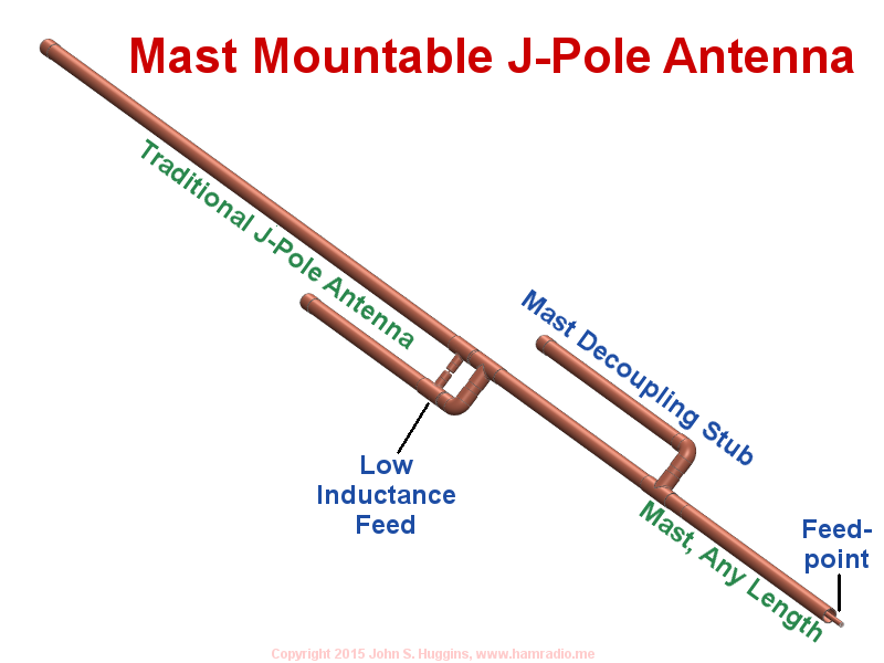
Figure 1 – Overview of mast mountable j-pole antenna
Figure 1 illustrates the typical j-pole with its radiating half-wave conductor and impedance transforming quarter-wave section. In addition you see a mast decoupling stub providing the critical mast isolation function. As well you can see the use of pipe-Ts at the “traditional feedpoint” to reduce the inductance of the feedline “spread” when connecting it to the j-pole. Finally there is a hint of internalizing the feedline to once and for all rid ourselves of the “flying feed” nonsense with a new feedpoint down below and along the mast.
Let’s turn, descriptively, to each proposed new technique.
Mounting-structure isolating 1/4-wave mast choke
The traditional j-pole vertical antenna provides no relief from radio frequency currents flowing along any connecting conductive structure. Therefore taming mast currents is job number one of any new j-pole design. Figure 2 outlines a practical method.
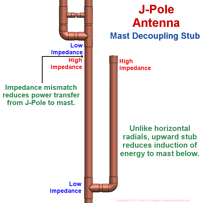
Figure 2 – J-pole mast decoupling stub
The addition of the lower stub presents a high impedance point to the low impedance of the bottom portion of the traditional j-pole structure. This difference in impedance and resulting impedance mismatch serve to choke off currents (or restrict power transfer) that may otherwise flow down the mast. Real measurements confirm this behavior.
What about radials?
Radials are an important feature in many antenna designs. Indeed, we can replicate the “mast choke” function with the use of 1/4 wavelength horizontal radials protruding from the same location as above. This will help choke the currents, but, like the vertical stub above, currents do flow in the stub or radials. This current will, in turn, induce currents in nearby conductors. This process induces currents beneath the classic 1/4 wavelength monopole antenna leading to the notorious elevation of the pattern from the textbook monopole’s doughnut shape. To avoid this effect, and to preserve the slim nature of the j-pole antenna, this design bends the stub upwards and parallel with the mast.
Hmm, this… looks… familiar…
If you’re thinking you’ve seen something like this before, you probably have. The above mast decoupling stub operates similarly to the cylindrical Bazooka balun portrayed by Balanis.[3] This collinear coaxial choke will also perform this task admirably, but not quite as simply as the copper cactus method above.
Low inductance feed
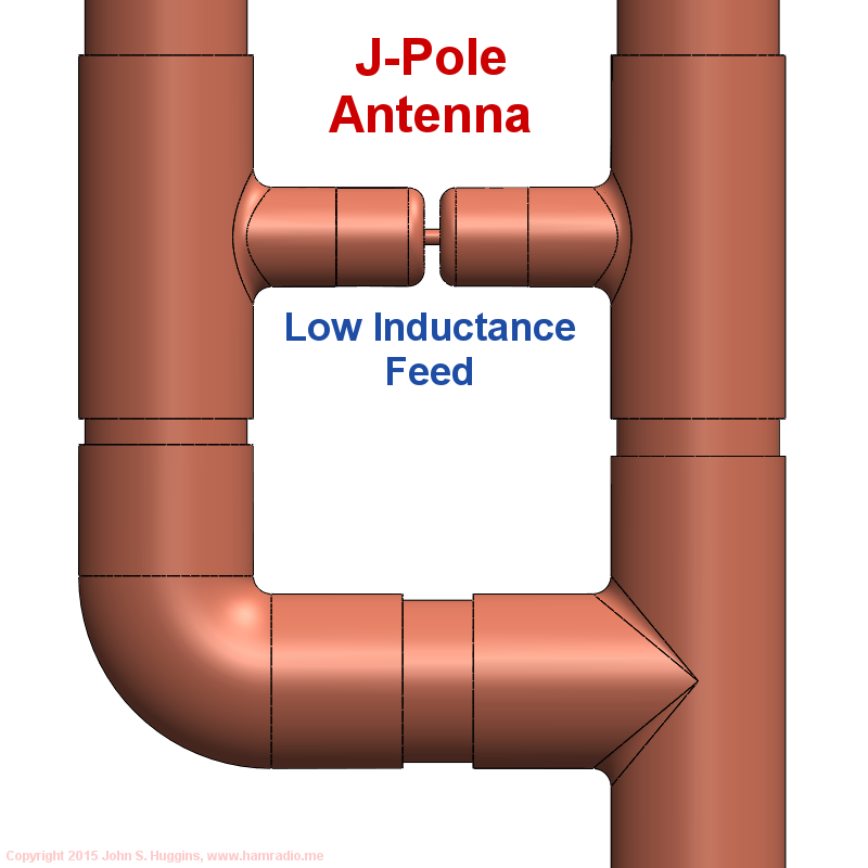
The traditional j-pole antenna flays out the transmission line to two thin wires that connect to each side of the parallel tubes in the matching section. Thin wires are more inductive and add this inductance to the natural feed impedance present on the antenna. The use of thicker conductors reduces the inductance leaving the feedpoint a narrow gap suitable for direct connection to feedline without the need to flay the ends. This is true with both an external and internal feedline. Figure 3 provides an overview…
Figure 3 – Front view of low-inductance j-pole feedpoint.
The “thick wire” approach is the classic way to lower inductance of any linear conductor. Indeed many j-pole builders use copper strap and other large conductors to mitigate this problem. Proper placement of this feed system along the quarter-wave matching section is as important as ever. The above proportions represent an approximate match to 50 ohm transmission line.
The “thick wire” tube approach also provides a solid mounting position for the feedline leads using clamps or equivalent attachment systems.
Integral feedline
One weakness in the traditional j-pole antenna is the external feedline connection to the feedpoint. Traditionalists who desire to adhere to well choked external transmission lines, but apply the above improvements will still have a j-pole antenna measurably superior to all previous attempts. The proposed mast mountable vertical antenna builds on internalizing feedline ideas from amateur radio operators[4][5], moves this transmission line inside the hollow conductive structure and secures it to mitigate feedline currents. Whether an internal coaxial cable or a coaxial transmission line made from the mast’s hollow structure (herein afterwards known as ‘Internal Coaxial Structure’), the line terminates at the low inductance feed. Two critical design features make this possible. Figure 4 reveals the first…
In this view we see the right feed point, the one connecting to the main central conductor of the antenna, is hollow. The integral feedline, described in detail below, passes up through the antenna mast, makes a 90 degree turn and emerges at this point. The design supports two forms of internal feedline: internal coaxial cable and internal coaxial structure.
Internal coaxial cable
If using an internal coaxial cable, the shield flays out and connects to the rim of the opening through the application of best practices. This is relatively simple with a good clean transmission path from the antenna’s bottom transmission line connector to the traditional j-pole feedpoint.
Internal coaxial structure
If the internal feedline is an internal coaxial structure, the opening is the terminus of the internal transmission line “shield.” There are two possible materials to fill the hollow space: air and a non-conductive dielectric.
Hollow space filled with air: An air-filled coaxial transmission line theoretically achieves the lowest loss. If a means to suspend the center conductor (below) is found, the short segment will be efficient.
Hollow space filled with a non-conductive dielectric: Practically speaking placing a filler material in the hollow space achieves mechanical support of the center conductor (below) and weather sealing. The dielectric properties will change the ratio of coaxial cable conductor dimensions.
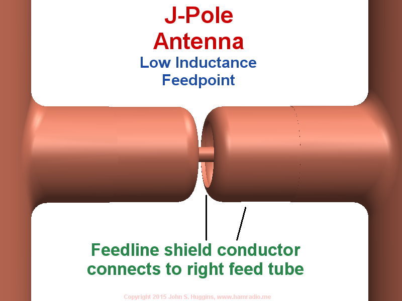
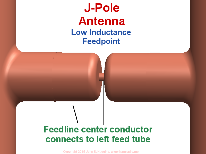
With either the internal coaxial cable or internal coaxial structure, the center conductor passes through the opening and connects to the solid face of the left feed point as seen in figure 5…
Figure 5 – Detail view of j-pole low inductance center conductor connection.
The end result is the energy flowing inside the transmission line is applied across the gap between the two feedpoint cylinders. A bit of sealant in the gap renders a weather resistant seal.
A perfectly reasonable question to ask is “What about feedline common-mode currents?” Let’s discuss the two methods of integral feedlines: internal coaxial cable and the internal coaxial structure.
Internal coaxial cable common mode currents
If you properly and completely terminate the shield of the coax to the rim of the hollow feedpoint tube (the right-side tube above) what happens? Keeping in mind the skin-effect depths at VHF+ frequencies are much much smaller than any conductive wall or shield in most every antenna design, we infer two things:
A coaxial cable terminating in the open can very easily, and most certainly does, suffer shield currents originating on the inside of the coaxial structure, wrapping around and flowing along the outside. What governs how much current flows on the outside is the impedance the outside surface presents to the point where the coax terminates in combination with the antenna impedance. This variable is based on transmission line length, where it connects, what is connects with, and other environmental factors.
A coaxial cable terminating where it emerges from inside the antenna, as shown in figures 4 and 5, has one very important feature… The electrical connection between shield and rim isolate the outer surface of the internal coaxial cable from external voltages and currents. Any tendency for currents to “wrap around” the end of the coaxial cable are applied solely to the antenna’s external surface. Since the antenna design includes a mast decoupling stub, there is no place for these currents to flow other than along the antenna elements.
Internal coaxial structure common mode currents
Similarly when the wall of the antenna tubing is the actual “shield” of the coaxial transmission line, any currents that dare to flow or “wrap around” are already outside, flow to the antenna and stay there thanks to the mast decoupling stub.
Self choking transmission line
The result of placing a coaxial transmission line inside the antenna is a self choking system free of the need to apply choke best practices to the feedline.
More about the internal coaxial structure
It would seem the easiest approach of internalizing the transmission line is to simply place a coaxial cable inside the tubes of the mast mountable j-pole antenna. The difficulty is how to apply best practices to ensure a continuous connection of the shield to the rim of the low inductance feed hollow tube. For the skin-depth theory to hold, this connection likely must be seamless. Superb examples are everywhere and include coaxial cable connectors with their various methods of captivating the shield to the connector shell.
One cannot ignore the exciting possibility of using the copper pipe in the classic copper cactus variations as an air dielectric coaxial hardline. Is it possible? Simulations (no, not NEC) run with an appropriate size inner conductor suggest it is possible. Figure 6 offers highlights…
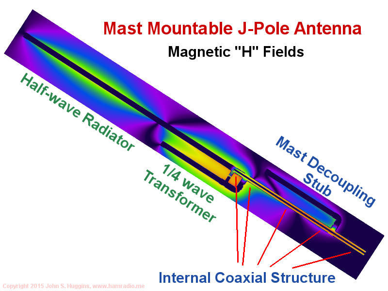
Figure 6 – Overview of mast mountable j-pole antenna
This busy graphic shows a snapshot of simulated magnetic “H” fields in a moment in time well after applying power to the bottom of the mast. Before talking about the internal coaxial transmission line, we can take a moment to appreciate the H-fields and how they reveal the high current points along the antenna. The half-wave radiator and 1/4-wave transformer are busy working like a j-pole should. Also note the reduction of current near and beneath the mast decoupling stub; This important component is doing its job well.
Now let’s focus on the transmission line within the pipe. If you look closely, you can see most of the pipe reveals no internal fields whatsoever. However, the points marked “Internal Coaxial Structure” have the appropriately proportioned inner conductor pipe arranged to yield an approximate 50 ohm transmission line. In this region you can see the resulting fields between inner conductor and the inner wall of the mast pipe.
A logical question is what happens at the pipe-T intersections. No effort is made to seal off the right angle opening. Do they perturb the operation of the inner transmission line? Figure 7 reveals the answer at the intersection of the mast decoupling stub and main mast…
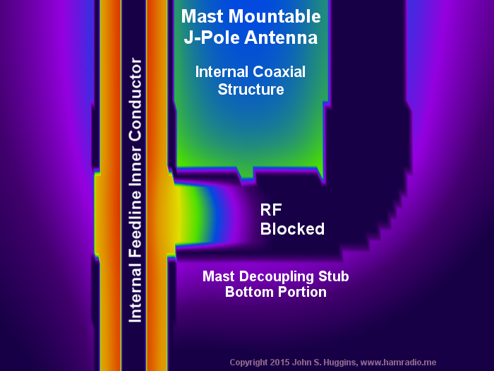
Figure 7 – H-fields inside pipe at mast decoupling stub
This simulation uses 146 MHz. If you consult publications from your favorite RF guru, Kraus, Balanis, Jasik, etc., you will learn that an empty pipe can, at certain wavelengths, become a waveguide. A two-meter wavelength is far too long to support any such mode within a conductive pipe with diameter much smaller than the radio wavelength. As we can see in the EM simulation, the empty tube at right angles to the inner transmission line attenuates the fields promptly. The fields, thus, propagate no further into and within the mast decoupling stub.
Of course there is a small disturbance. The simulations to date reveal no perceptible effect on the utility of the transmission line. I suspect this is no worse than using a PL259 for VHF. Real tests are forthcoming to verify.
Now let’s have a look at the top end of the internal feedline in Figure 8…
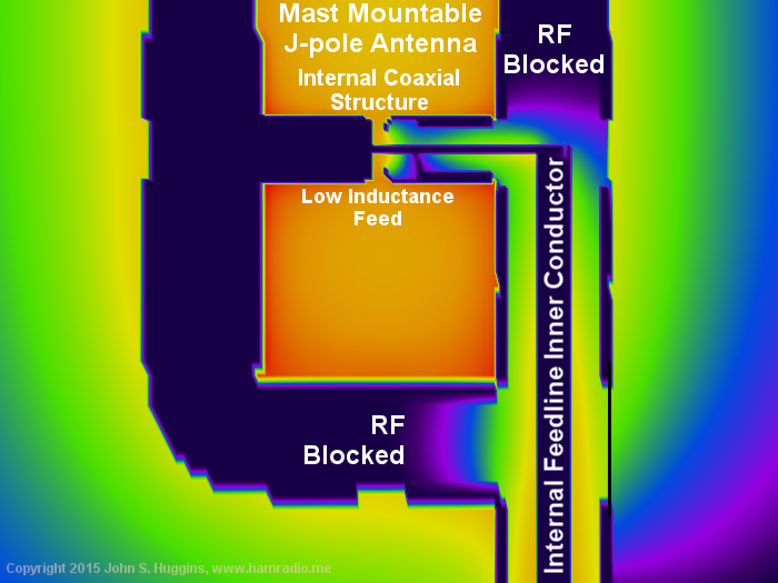
Figure 8 – H-fields inside pipe at Low Impedance Feedpoint
Once again we see attenuation where the pipe no longer has an inner conductor. This is true as well at the top of the internal feedline inner conductor where the fields propagate no further. Note at this spot a properly proportioned horizontal inner conductor “wicks” the RF energy into the smaller diameter conductive pipe of the low inductance feed. This in turn delivers power to both sides of the air gap between the feed points. As the small diameter conductive pipe is the actual shield of the transmission line, the wrap-around currents literally flow onto the antenna with nowhere else to go.
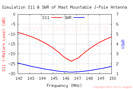
How well this works in real life remains to be seen. Simulations offer hope and great expectations. The bottom feedpoint S11 and SWR simulation of this 146 MHz example of the mast mountable j-pole antenna dips nicely to -23 dB as seen in figure 9…
Figure 9 – S11 and SWR of Mast Mountable J-Pole
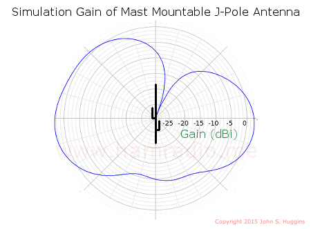
Figure 10 shows the elevation gain pattern simulation of the mast mountable j-pole antenna. The classic slight lopsided nature of the standalone j-pole is visible despite the mast’s presence.
Figure 10 – Elevation gain pattern of Mast Mountable J-pole
The simulation method used for the above is an FDTD technique, not MoM NEC. FDTD provides a way to simulate the integral coaxial structure with some degree of success. The simulation injects the RF at the very bottom of the antenna to simulate the entire path to the low impedance feed along with the exterior antenna surfaces. Balancing Yee-cell size with processing resources is a tradeoff, but the above results show the idea for this antenna design has promise. The very next step is a full size prototype for VHF or UHF bands.
Feedpoint connection locations
Connecting a feedline to the antenna involves terminating the bottom of the internal feedline at a connector either at a pipe end-cap or, perhaps, at a T connection. Let’s review two possible scenarios:
Bottom feed: If the protruding mast (the “Mast Any Length” of figure 1) is only long enough to allow parallel strapping to a support-mast, the logical connection point is the bottom of the antenna mast. A conductive tube end-cap is machined to accept a bulkhead RF connector of the user’s choice. The center conductor of the RF connector attaches to the internal feedline inner conductor. The RF connector’s shell mates to the end cap and thus the copper tube via best practices. The transition from coaxial cable to integral feedline is seamless.
Side Feed: If the designer desires the “Mast Any Length” of figure 1 to be much longer, perhaps becoming the guyed antenna support all the way to ground, a pipe-T may be placed near the bottom. A pipe end-cap with connector, as described above, is placed on the side pipe-T opening. A horizontal coaxial conductor properly proportioned to the size of the pipe-T’s inner diameter, joins the connector center conductor to the internal feedline inner conductor. This pipe-T connection replicates the horizontal “wick” explained in figure 8 and routes RF power from the side-mount connector to the internal feedline inner conductor. Thanks to waveguide blocking, the mast can continue beneath this pipe-T to any length providing the designer the option to place the antenna system coaxial feedpoint at a convenient height.
The above scenarios highlight the internal coaxial structure approach. Similar results are available using the internal coaxial cable approach; Best practices apply concerning bulkhead mounting the coaxial cable and connector.
While the above two examples will likely be the majority of methods used to “connectorize” the mast mountable j-pole antenna, other scenarios likely exist. All share the convenience of choice of where to place the antenna system’s connector.
Summary
Mast decoupling stub – a must have improvement
Taken alone, the novel mast decoupling stub solves the legendary problem of mast currents flowing from a traditional j-pole antenna to its structure. While this stub does complicate the j-pole a bit, it is a solution that maintains the sleek appearance most of us enjoy. Bending the stub provides a benefit over radials with a reduction in induction to the mast. If you are going to build a j-pole antenna that will mount to a conductive structure, the mast decoupling stub is a must have feature.
This isn’t just theory; Measurements confirm the tendency of mast currents to flow at will and the ability of the stub to quell them.
Note standalone j-poles with only a feedline and no conductive mounting structure do not need a mast decoupling stub. Examples include ladder-line style portable j-pole antennas and copper J-poles that have insulating mounting structures.
Low inductance feed
While not absolutely necessary, the novel low inductance feed tubes remove a bit of series inductance and provide a solid mounting point for an external feedline. The low inductance feed is a built-in feature of the internal feedline options.
Balunless feedline
Internalizing the feedline offers the promise of a no choke system. This works in theory and in simulation. Real tests are forthcoming.
Entire antenna at same potential
Every portion of the mast mountable j-pole antenna connect together with thick conductive pipes or tubes resulting in low resistance between every portion of the assembly. With appropriate connection to an earthed conductive mast, this antenna is at dc ground.
Déjà vu
Does any of this look familiar? Griffith found similar results by moving the feedpoint to the middle of the upper halfwave radiator in his spiffy dual-band antenna[6]. He mentions…
The antenna’s main vertical element [. . .] is about 1/2 [wavelength] long at 146 MHz and employs a 1/4-[wavelength] stub at the bottom to decouple the main element from the mast and feed line.[6]
Griffith alleges moving the feed off the J portion leaves it to perform the task of a mast decoupling stub, but doesn’t notice the stub fails to place a high impedance against a low impedance, but rather matches the high impedance of the bottom radiator to the stub hence encouraging current flow. As the coaxial feedline is internal to the main pipe, any common mode current tendencies are dependent only on how well the shield connects to the circumference of the pipe at the feedpoint.
Conclusion
The problems with traditional j-pole antennas are crystal clear to folks who bother to test them with an open mind. The above improvements may breathe new life into a legendary (or notorious) design. The builder will achieve a fully dc grounded antenna without compromising the antenna pattern at the design frequency.
Application
What use does anyone have for an antenna made from 100% conducting materials? The applications and objectives of the j-pole design amendments described above will:
provide a Mast Mountable Vertical Antenna for providing a rugged, weather tolerant vertical antenna that will not be compromised by the antenna mounting structure;
provide a Mast Mountable Vertical Antenna that preserves the radiation pattern of the active antenna element in the presence of the antenna mounting structure;
provide a Mast Mountable Vertical Antenna that eliminates the vulnerable external feedline associated with j-pole style antennas;
provide a Mast Mountable Vertical Antenna that mitigates the inductance of the traditional j-pole feedpoint;
provide a Mast Mountable Vertical Antenna that suppresses the conduction of radio frequency currents to the antenna mounting structure;
provide a Mast Mountable Vertical Antenna that suppresses the induction of radio frequency currents to the antenna mounting structure;
provide a Mast Mountable Vertical Antenna that provides a dc short between the antenna feedpoints;
provide a Mast Mountable Vertical Antenna that provides a dc short between the antenna feedpoint and the antenna mounting structure;
provide a Mast Mountable Vertical Antenna that provides a dc short from every portion of the antenna to the antenna mounting structure;
provide a Mast Mountable Vertical Antenna that facilitates a feedpoint connection below the antenna;
provide a Mast Mountable Vertical Antenna that suppresses the conduction of radio frequency currents along the feedline;
provide a Mast Mountable Vertical Antenna that suppresses the induction of radio frequency currents along the feedline;
provide a Mast Mountable Vertical Antenna that provides a mechanically robust antenna structure;
provide a Mast Mountable Vertical Antenna that eliminates the use of insulating materials in the load bearing antenna component;
provide a Mast Mountable Vertical Antenna that maintains the slender nature of the j-pole while mitigating the well known induced currents issues;
provide a Mast Mountable Vertical Antenna that conducts lightning surge energy on any part of the antenna to the antenna mounting structure;
provide a Mast Mountable Vertical Antenna that facilitates a preferential path of lightning energy through the mounting structure and a less preferential path of lighting energy through the feedline;
provide a Mast Mountable Vertical Antenna that functions in the presence of conductive paints and other treatments;
provide a Mast Mountable Vertical Antenna that is made entirely of conductive materials;
provide a Mast Mountable Vertical Antenna that is made by transforming an existing conductive mast with the addition of two 1/4 wavelength parallel conductive stubs.
Perhaps the j-pole antenna has a commercial future after all.
…I now have a 2m version built. Real chamber measurements for this 2m monster are complete and will be in an upcoming article. I built the 2m version with the decoupling stub unsoldered so I can test with and without. It makes a measurable improvement albeit a small one with the short mast (this thing barely fits into the chamber as is).
Link corrected… many thanks for that. Keeping up with link changes is almost a full time job it seems.
Interesting reading, I think you may have it covered, just a few more practical hurdles to go.
I just built a j pole for 11m, my first. I have incorporated some of the principles you mentioned in your earlier articles which of coarse includes the decoupling stub.
First impressions suggest the antenna works quite well, some further tuning is required though.
Thanks.
Jeremy.
Does it matter the length of the mast decoupling stub? Is it a 1/4 wave? Also does it matter the distance of the decoupling stub from the mast mounting stub. Also at the antenna feedpoint would it work to peel back the coax and fold the shield over the t connector?
Yes it is approximately a quarter wave in length. The real dimension to consider is the total distance, electrically, from the tip of the mast decoupling stub to the point just below the J of the traditional J antenna which should be one half wavelength in total length.
I have followed this post and have re-read it many times. I am intrigued by the design and have most parts cut to make it in a 2M size. I also am unclear about the dimensions relating to the mast decoupling stub. I understand that the stub is "about" a quarter wave in length. However, your response to cj calhoun still leaves me scratching my head! I must be missing something, but the graphics do not seem to represent the distance "from the (upper?) tip of the mast decoupling stub to the point just below the J of the traditional J antenna" anywhere near 1/2 wavelength. Can you please clarify?
Another way to think of the mast decoupling stub is a parallel transmission line 1/4 wave in length. The regular J-stub and the mast decoupling stub are mostly identical in size and perform similar tasks… their use is what's different. I do have a mock up of a 2m at work and it seems to quell mast currents considerably. I will measure it later today and report here.
Thanks for the great article on the 'new and improved' J .
Would the use of 3/4" heavy wall copper tubing change any calculations used in determining measurements for this antenna?
Also, would isolating the 'any length mast' of the J from the conductive support mast by means of insulating rubber shields at the points of contact under the straps clamping the two together effectively work ? Or perhaps a length of PVC over the metal mast?
I built one prototype for 2m that works well although it uses the internal coaxial cable technique rather than making the tube itself the transmission line. The patent just received approval and will publish in a few weeks. I will work on a 445 MHz model with 1/2 inch copper tubing first and see where that goes.
I am very much intrigued by this antenna. It seems to have a lot of potential. One concern I have is that it might be difficult to thread a high quality coax through the bends. Being a bit of a noob, I'm going to go out on a limb and ask you more seasoned hams what might happen if one were to modify the design to enable the use of copper 45's to allow for those bends. Would the antenna still operate if the vertical elements were joined by horizontal elements that were slanted at a 45 degree angle?
In the prototype with 3/4 inch tubing it was a bit difficult to arrange the coaxial cable within, but it did work. The larger problem is soldering the final piece of copper at the feed point with the cable inside. The large amount of heat moving through the pipes might damage the coax. I'm still working on a solution for that, but what I'm really hoping to finalize is the scheme using the pipe itself as coaxial transmission line.
The stub should work at or near the third harmonic, just as the radiator and impedance transformer section does, but the awkward beam angles put this as a low priority at this time.
Excellent article. Have you found a difference in performance if the coax center feed conductor is on either side of the 1/4 wave transformer?
Also, do you use conductor centers or the edges for your measurements. I've noticed a difference depending one which online source you look at.
Thanks!


Great write up. Did you ever get around to testing it?
FYI the link to Griffith's dual band antenna is broken. It has moved here: http://www.n5dux.com/ham/files/pdf/146%20and%2044…
Thanks for the compliment. In addition to the 1 GHz prototype in the previous article…
http://www.hamradio.me/antennas/j-pole-antenna-gr…
…I now have a 2m version built. Real chamber measurements for this 2m monster are complete and will be in an upcoming article. I built the 2m version with the decoupling stub unsoldered so I can test with and without. It makes a measurable improvement albeit a small one with the short mast (this thing barely fits into the chamber as is).
Link corrected… many thanks for that. Keeping up with link changes is almost a full time job it seems.
Interesting reading, I think you may have it covered, just a few more practical hurdles to go.
I just built a j pole for 11m, my first. I have incorporated some of the principles you mentioned in your earlier articles which of coarse includes the decoupling stub.
First impressions suggest the antenna works quite well, some further tuning is required though.
Thanks.
Jeremy.
Does it matter the length of the mast decoupling stub? Is it a 1/4 wave? Also does it matter the distance of the decoupling stub from the mast mounting stub. Also at the antenna feedpoint would it work to peel back the coax and fold the shield over the t connector?
Yes it is approximately a quarter wave in length. The real dimension to consider is the total distance, electrically, from the tip of the mast decoupling stub to the point just below the J of the traditional J antenna which should be one half wavelength in total length.
I have followed this post and have re-read it many times. I am intrigued by the design and have most parts cut to make it in a 2M size. I also am unclear about the dimensions relating to the mast decoupling stub. I understand that the stub is "about" a quarter wave in length. However, your response to cj calhoun still leaves me scratching my head! I must be missing something, but the graphics do not seem to represent the distance "from the (upper?) tip of the mast decoupling stub to the point just below the J of the traditional J antenna" anywhere near 1/2 wavelength. Can you please clarify?
Another way to think of the mast decoupling stub is a parallel transmission line 1/4 wave in length. The regular J-stub and the mast decoupling stub are mostly identical in size and perform similar tasks… their use is what's different. I do have a mock up of a 2m at work and it seems to quell mast currents considerably. I will measure it later today and report here.
Thanks for the great article on the 'new and improved' J .
Would the use of 3/4" heavy wall copper tubing change any calculations used in determining measurements for this antenna?
Also, would isolating the 'any length mast' of the J from the conductive support mast by means of insulating rubber shields at the points of contact under the straps clamping the two together effectively work ? Or perhaps a length of PVC over the metal mast?
I am interested in building this antenna.
Does anyone have specific implementation suggestions? things to avoid?
What did you use for the internal conductor? How did you attach a connector to the feed point?
Do you have any photos of your finished product?
Thanks
Ken
I built one prototype for 2m that works well although it uses the internal coaxial cable technique rather than making the tube itself the transmission line. The patent just received approval and will publish in a few weeks. I will work on a 445 MHz model with 1/2 inch copper tubing first and see where that goes.
I am very much intrigued by this antenna. It seems to have a lot of potential. One concern I have is that it might be difficult to thread a high quality coax through the bends. Being a bit of a noob, I'm going to go out on a limb and ask you more seasoned hams what might happen if one were to modify the design to enable the use of copper 45's to allow for those bends. Would the antenna still operate if the vertical elements were joined by horizontal elements that were slanted at a 45 degree angle?
In the prototype with 3/4 inch tubing it was a bit difficult to arrange the coaxial cable within, but it did work. The larger problem is soldering the final piece of copper at the feed point with the cable inside. The large amount of heat moving through the pipes might damage the coax. I'm still working on a solution for that, but what I'm really hoping to finalize is the scheme using the pipe itself as coaxial transmission line.
I wonder if you could add another short stub as a trap for better dual band performance?
The stub should work at or near the third harmonic, just as the radiator and impedance transformer section does, but the awkward beam angles put this as a low priority at this time.
Excellent reading.. you have given me a whole new train of thought on feed and matching, looking forward to doing some experimenting.
Thank you
Hello All, I am interested in purchasing his type of antenna for GMRS and 2 meter usage. Any and ALL help is greatly appreciated. Thank You.
Excellent article. Have you found a difference in performance if the coax center feed conductor is on either side of the 1/4 wave transformer?
Also, do you use conductor centers or the edges for your measurements. I've noticed a difference depending one which online source you look at.
Thanks!