Abstract
The end-fed half-wave antenna can function alone, but feed lines are the norm regardless. Habits born form the use of center-fed half-wave antennas do not apply to the end-fed case… but they almost do. Simulations suggest what feedline lengths to avoid and offer a confirmation why portable users with short feeds never seem to have trouble.
The no-feedline EFHW
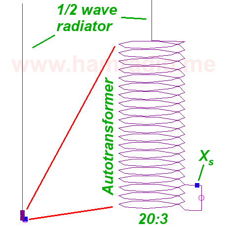
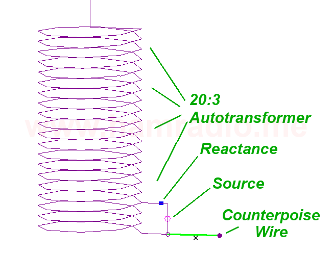
In the previous article featuring a standalone EFHW with autotransformer we confirmed the end fed half-wave antenna can function with practically no feedline. Figure 1 below shows the business end of the end-fed dipole with source and series reactance Xs (a capacitance) combine to yield a 50 ohm feed impedance for the source.
The “Counterpoise” wire missing from the previous article’s model now comes into play in the simulations performed for this article as seen in figure 2.
The term “counterpoise” in this configuration is a misnomer since the definition implies it is designed into an antenna system purposely to make it function. Since no such requirement exists, we really are just talking about dealing with the feedline and should not call it “counterpoise.” It’s a hard habit to break.
Onward.
Extra wire makes a difference
What quickly became apparent by adding just 1 cm of “feedline” is the behavior of the system changes. It changes enough to warrant tweaking of the antenna length and reactance value. Based on the discoveries discussed below, I refactored the antenna with the horizontal wire open-end about 50 cm from the dipole as that was found to be a very stable length. More details on that later. Figure 3 shows the model variable parameters highlighting the differences: no “counterpoise” wire on left, about 50 cm on right.

As you can see the differences are small, but enough to invite tweaking.
4nec2 auto segmentation a must
If you decide to run this model on your own computer while sweeping the horizontal wire length, you are well advised to set the auto segmentation value to about 151 segments per half-wave. This is just about right to ensure the horizontal wire always has the proper amount of segments, but doesn’t change the coil or vertical dipole element segmentation. Figure 4 shows the model with about 50 cm of horizontal wire with and without segments dots to give you an idea what’s going on.

Half wavelength “feed line” – a problem

As you can see above, a feed line length that mirrors the high impedance of the end of the horizontal wire to the feed point entices current from the system. It’s time to vary the length to examine the effect on antenna characteristics.
Simulating feedline both open and grounded
Figure 6 and 7 show the simulation two ways: one with the horizontal wire simply open ended and again with two 1/4 wave wires arranged to produce a low impedance, fake ground, point. The latter situation is probably the more realistic situation, but I wanted to explore both scenarios.
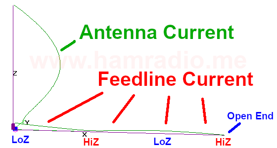
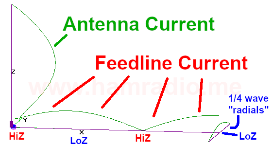
In the particular lengths shown in figure 6 and 7 you begin to see a theme where current flows when a high impedance touches the autotransformer of the EFHW. Figure 6 has little current on the feedline while figure 7 has lots. With the above two situations in mind, it’s time to explore antenna characteristics as the feedline changes length.
Reflection coefficient vs. EFHW feedline length
Let’s view VSWR and Return Loss of the antenna feed point vs. feed line length. Bear in mind the simulation feed point “NEC source” is always at the autotransformer end of the “feed line.” The horizontal wire is simply the effect of the shield of said line, be it open or “grounded.”


It pays to study the above two graphs more than once. Key takeaways include:
- Certain lengths perturb operation. For example a quarter-wave (1/4 of 2m wavelength) of grounded wire “messes with” the antenna’s reflected power.
- Many lengths have measurable, but nonetheless minimal impact on the antenna’s reflected power.
- Nowhere is the reflected power a show stopper, but the speedy onset of poorer values around certain lengths gives reason for unease.
- A repetition of these conditions occur every half-wavelength.
So we can see there are plenty of feedline lengths that play nice with our EFHW antenna, but with particular lengths we best avoid depending on the grounded or ungrounded circumstance of the “radio end” of the feedline.
Gain vs. EFHW feedline length
A general premise is when current flows from the antenna feed point to the feedline, some power is robbed from the primary antenna radiator. Energy from the radiator is thus less. Therefore we can state where gain from the primary aerial wanes, power and thus current flows on the feedline. In the real world other losses may play a significant role, but keep in mind the lossless nature of this particular model made only of PEC wire and an ideal capacitor.
Figure 10 shows how we measure the gain from the primary radiator while ignoring the radiation from the feedline.

The following graph plots only the E-Plane gain of the theta (Vertical) polarization. This trick ensures we aren’t adding Phi (horizontal) polarization that certainly occurs from currents along the feedline. Yes this is precisely why I arranged the EFHW aerial and feedline orthogonal to each other. Let’s see some results in figure 11.
 of EFHW vs. feed line length")
I don’t have a graph or equiv. that shows this, but I observed where the gain is minimum, current along the feedline is maximum. You can see this for yourself by simulating the model in your copy of 4nec2 varying the SY variable “CoaxLeadLen” in the source file.
Longer still…
For some perspective here are the same variables of figure 11 with feedline length extended to 5m.
 of EFHW vs. feed line length")
Long story short, we want gain/efficiency and there are certain feedline lengths that impede this goal. Again, however, the good news is there are many lengths where this system remains effective. With this knowledge in hand, we can avoid feedline lengths that increase feedline currents.
Let’s check a real antenna product
The previous measurements of the Diamond NR770HBNMO end-fed 2m/440 antenna with K515 luggage rack mobile mount reveal an EFHW antenna that works just fine as this measurement confirms…

Keep in mind the above is from measurements, not simulation. The NR770 works quite well. The K515 mount’s instructions implore the installer to ensure the mount is electrically isolated from any structural element using the provided rubber like sheet. The K515 comes with an interesting length of RG316 feedline.
The peculiar length of the Diamond K515 feedline
When one purchases an antenna from the candy store, we often see feedline with lengths of 12, 15, 16 feet. No big deal right? Curiously the K515 comes with 13.5 feet of feedline.
13… POINT… 5!
Why such an odd length?
Let’s assume for the moment only the “grounded” end of the feedline situation applies in Realville. Let’s plot the same gain information from figure 12 with various feedline lengths noted in boxes of width sufficient to account for 0 to 5% dielectric reduction of Vf.

Is Diamond Antenna telling us 13.5 feet resides in an optimal feedline length “window” for EFHW antennas? It’s hard to say, but this is interesting.
Conclusions
EFHW antennas work with caveats
These simulations (and a whole lot of real world experiences by users plus measurements by me) suggest end-fed half-wave antennas do work just fine, but are not immune to certain feedline (or any other mounting structure) lengths. The critical moments are when the extraneous conductors present a high impedance to the base of the autotransformer. Think impedance match. These points are relatively easy to avoid given the large swaths of lengths that produce little perturbation of antenna performance.
Opposite center fed antenna behavior
This behavior is quite opposite the situation of more traditional antennas where feedline/structure currents flow when they present a low impedance to the feed point. We all know this right? Who hasn’t heard about mitigating these currents with an appropriate ferrite choke or equivalent.
Shorter feedline users can worry not
The 2m case of this study aside, one key takeaway from the graphs above is any feedline less than 1/4 wavelength avoids the problem lengths entirely regardless if the user grounds the transmitter or not. This validates the successes of many users of HF EFHW antennas such as the LNR EF-10/20/40. The shortest band is 10m so a feedline of under 2.5m (8 feet) should be just fine. Most portable EFHW operators use quite a bit less. Portable EFHW = NBD.
Longer feedline users can plan accordingly
As Diamond Antenna might have done with their K515, we can plan our feedline routing and such to avoid the problem areas. This includes strategic placement of choke impedances at high current, low voltage points. Or just put two chokes 1/4 wavelength apart. Do whatever it takes to ensure a current loop (low current, high voltage, high impedance) point isn’t impressed at the antenna feed point. Think it through and you are probably good to go.
EFHW antennas can stand alone, but…
The simulations for this article, an earlier article, and especially the previous article confirm the EFHW resonates without need for something to “push against” as many espouse on the various ham watering holes… or so simulation says. An experiment will help. Yeah the feed end of an EFHW antenna is hot with E-Fields and such, but there is nothing I can find about good ole Maxwell that precludes this from functioning.
All that said, I’ve accepted a challenge from Zed Heads to perform an A-B comparison of a center-fed and end-fed dipole using no coax with as small a transmitter as possible. Stay tuned for an actual live experiment to confirm (or not) the output power of a coaxless dipole is not radically different no matter where it is fed. It’s worth the effort to find out for sure don’t you think? Wait no more… here is the data from the experiment.
The figure 8 – blue line (grounded end) is exactly what I am experiencing with my end fed strung at my back yard. I was experimenting with various counterpoise lengths yesterday with my 40m end fed. 10m counterpoise produced excessive impedance at the end fed transformer secondary, which the transformer was not designed to match. Either shortening the counterpoise to 6m or extending to 15m brought the antenna back to the impedances that the end fed transformer was able to match reasonably.
It strikes me that I have not seen this kind of analysis of end feds. Often a shorter than lambda/2 counterpoise is recommended as sufficient, and I have seen multiple analysis that over a real ground a somehow shorter radials than lambda/2 are most effective, but I have seem multiple recommendations of lambda/2 counterpoises to be used with an end fed antenna, which based on your simulations and on my experience seems not a good idea in general case.
Thank you much for your observations suggesting some correlation between my simulations and reality. Yours are the first I've seen.
If nothing else falls out of this research, at least users of EFHW antennas have a recipe for logical deployment.