The never ending story
Despite overwhelming evidence to the contrary, all antennas must include in its design an ability to handle and minimize common mode current down the feed line and mounting structure. The radials on the quarter-wave monopole antenna are a prime and easy to understand example of how to do this.
J antennas have no such feature
Despite the well entrenched folklore, the J antenna is missing critical features to mitigate common mode currents. In essence, the J has nothing equivalent to the radials on the quarter-wave monopole. Many mistakenly believe the quarter-wave matching stub also serves the purpose of decoupling stub. It doesn’t. I’ve obsessed about this on this site at length.
Time to obsess a bit more about the J antenna
I purchased a variety of roll-up J antennas from various vendors for a forthcoming review. All include some form of choking impedance on the feed-line… just kidding. Amazingly one does not ship with the necessary ferrite or other device… no really. Figure 1 examines a logical reaction.

J antenna test setup
Into the chamber went this choke-less wonder hung from a PVC yard arm atop a PVC mast stuck into a metal tripod. The bottom of the J antenna was 60 inches (about 3/4 wavelength) above the chamber floor. The feed-line was dressed straight down with extra coax coiled and taped flat to the floor. The antenna and its line hung to the side about 18 inches and parallel to the vertical PVC mast. Three type 61 clamp on ferrites were added to the coax just above the floor. Figure 2 provides a schematic view of the setup.

Effectively, the J antenna is in the clear well above the conductive tripod, but the feed-line isn’t. This arrangement was on purpose. We shall see why below.
Ferrites on the floor?
Why yes. The ferrites on the floor place a high impedance at 3/4 wavelength from the antenna feed-point. This converts to a low impedance at the feed-point to better entice common mode (CM) current. This is required since feed-line circumstances vary the impedance presented to the feed-point hence varying the level of “enticed” common mode current… sometimes eliminating it by chance. This is why un-choked antennas often work fine in many circumstances despite being susceptible to CM current pattern skew. In this case, the ferrites 3/4 wavelength from the antenna force the worst case scenario so we can examine the effects of common mode currents more predictably.
Rollup J antenna measurements
To wit, figure 3 shows the E-plane gain along the plane through the roll up J antenna and the mast of figure 2.
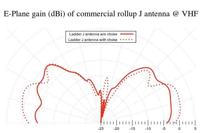
For the purists, and since it matters in this discussion, the view above is from the “other side” of figure 2… antenna and feed-line are to the right of the mast/tripod.
Bearing in mind the gain numbers presented above include whatever loss is in the antenna feed-line, I wouldn’t pay much attention to the absolute gain. Its the difference between the two patterns that matters in this analysis… and what a difference we see! Highlights include:
- Common mode currents perturb the, antenna-as-shipped, pattern (solid red trace) greatly.
- The radiating feed-line and the conductive speaker stand interact causing pattern asymmetry.
- When a ferrite choke is added to the system directly beneath the antenna, the pattern stabilizes to what you expect for a vertical dipole at some elevation above ground (dashed red trace). Quite lovely actually.
- Since the commercial J antenna is well above the conductive speaker stand, interaction between them should be not, and is not, apparent… or at least mostly so.
Rollup J antenna test thoughts
This test was conceived with care to detect when feed-line currents contribute to the radiation pattern of the entire J antenna-feed system. If the feed-line were long enough, we would see an upward tilt of radiation much like a vertical long wire. Facilities are only so big so height is a limiting factor at VHF wavelengths. The conductive speaker stand nicely interacts with the feed-line while the antenna is well above and out of the way giving us a potential method to spot a difference. The results confirm the tendency of the the J antenna to seriously aggravate the antenna pattern. It is true feed-line circumstances often present a high impedance to common mode currents, but any antenna design lacking features to prevent this 100% of the time is an incomplete design. Notoriously, the J antenna is one such design. However the fix couldn’t be more simple… snap on a ferrite or two… done… at least for VHF where a properly selected ferrite can help.
Sure common mode currents are not always the “bringer of devastation” to your radio antenna system, but come on man… how hard is it to clamp a choke or two to a feed-line and worry not? Feed-lines are antennas too unless you ensure they are not by design.
Conclusion
Thankfully most of the roll-up J antenna vendors out there know to place some form of choke on their feed-line and ship exactly that way. Despite the nearly universal cluelessness with regards to antenna performance metrics (6 dBi gain = SMH!!) trumpeted by most of these vendors, they do wind up with a product that produces a VHF dipole of about 2 dBi in the air where you want/need it. They really do work.
What about UHF performance claimed by some vendors? Well… that’s another story for another post. Short answer… not good. Stay tuned.
When shopping for your roll up J antenna, ensure a good feed-line choke is part of their design. Otherwise question the integrity and/or knowledge of the maker. Blunt and sad, but true. Buyer beware.


"Despite the well entrenched folklore, the J antenna is missing critical features to mitigate common mode currents. In essence, the J has nothing equivalent to the radials on the quarter-wave monopole. Many mistakenly believe the quarter-wave matching stub also serves the purpose of decoupling stub. It doesn’t. I’ve obsessed about this on this site at length."
"… the J antenna is missing critical features to mitigate common mode currents…" because it's not a whole, proper antenna and choking it doesn't make it so!!
Why keep building and promoting these pieces of crap?
"because it's not a whole, proper antenna and choking it doesn't make it so!!"
By the same reasoning, neither is the quarter-wave ground-plane antenna, but they can be made more functional with an additional set of radials or equiv… just like the J antenna… and that's only if they need a connection to a conductive mast. Independently, both are whole and proper antennas and the rollup J antenna, yes with a feedline choke, personifies the near ideal antenna.
"Why keep building and promoting these pieces of crap?"
Well because they aren't bad as tests and research easily confirm. Yeah they have their idiosyncrasies like any antenna topology, but work fine in the hands of the skilled.
…"but work fine in the hands of the skilled"…
BRAVO!
Thank you for the informative presentations – appreciated.
Stay SAFE!
73
Nigel ZS6RN ex G8DEV L-o-n-g time ago.